Research Article - Biomedical Research (2018) Volume 29, Issue 8
Spectrum sensing+PUEA mitigation=>effective E-health management
Avila Jayapalan1*, Prem Savarinathan2, Venkateswarya Udayakumar1, Subashree R1 and Padmapriya Praveenkumar1
1Department of ECE/SEEE, SASTRA University, Thanjavur, Tamil Nadu, India
2School of Mechanical Engineering, SASTRA University, Thanjavur, Tamil Nadu, India
- *Corresponding Author:
- Avila Jayapalan
Department of ECE/SEEE
SASTRA University
Thanjavur, Tamil Nadu, India
Accepted date: February 19, 2018
DOI: 10.4066/biomedicalresearch.29-17-3540
Visit for more related articles at Biomedical ResearchAbstract
Dynamic spectrum management has the advantage of well-organised assignment of channels. But analysis shows that still the spectrum is not used efficiently always. For the proficient management of this valuable spectrum cognitive radio has proved to be a helpful tool. The main function of the cognitive radio is to sense the availability of the spectrum for its occupancy. So spectrum sensing becomes the prime task. This sensing process by a cognitive radio is interrupted by malicious user who is also a cognitive radio but selfish in gaining the access of the spectrum. Hence a helper node based authentication scheme has been proposed. Authentication based data transfer is achieved by the inclusion of tag in the data send by the helper node to the cognitive user depicting the absence of primary user. The authentication tag is generated using Bhutasankya algorithm and Katapayadi algorithm and embedded in the error control code block of Orthogonal Frequency Division Multiplexing (OFDM) based helper node. Utilizing the sensed spectrum, patient information is transmitted to the hospital from the remote location. This avoids the travel need to be made by the elderly persons from the remote center to the hospital for further consultation. To gain the advantage of re-programmability, the authentication scheme is implemented on Cyclone II FPGA.
Keywords
Cognitive radio, Helper node, Malicious user, Authentication, Convolutional code, Trilayered authentication tag, Arduino, Cyclone II FPGA
Introduction
The growing demand of radio spectrum has given it a chance to be a part of future trends also. Extant allocation techniques could not be effective since the necessity for spectrum has been growing. Thus this problem has brought the cognitive radio solution into light. And to solve the inflexibility of spectrum allocation in traditional wireless communication systems, Cognitive radio (CR) has come out to be a potential solution [1]. This technique helps in giving the secondary users (SU’s) a chance to use the frequency bands when the licensed primary users (PU’s) are idle [2].
Sensing the existence of the PU’s transmission has been an important technical challenge, i.e. the spectrum holes. Matched filter, cyclostationarity detection, energy detection and lastly wavelet detection are the trending detection techniques [3-7]. In these methods if the signal that is captured has the energy greater than the threshold, it is recognized as a PU’s signal. Particular characteristic of a captured signal such as cyclostationarity and a synchronization word are to be found by secondary users in the feature detection techniques. The captured signal is recognized as a PU, if the characteristic is sensed.
Apart from primary users and secondary users there are also some selfish users called malicious secondary users present in the same environment [8]. Malicious users are those who wish to access the free spectrum in the absence of primary user. To overcome the primary user’s sensing techniques, the attacker will send signals having high power or imitate specific characteristics of a primary user’s signal (e.g., synchronization words or utilize the similar pilots). This will lead the secondary user to mistake the attacker for a primary user and will not employ related channels. These attacks are termed as Primary User Emulation (PUE) attacks [9]. In this attack, the attacker imitates as the PU and convinces the SU’s that the PU is utilizing the spectrum though they are not [10].
Therefore to avoid these attacks, a safe primary user sensing technique that will differentiate between an attacker and a PU signal is required. FCC stated that “No changes of the present system (i.e., PU) should be necessary to have room for the opportunistic utilization of spectrum by SU’s”. Hence modification could not be done to the PU signal. So the solution to overcome FCC rule is the inclusion of helper node between PU and cognitive receiver [11,12].
Proposed Methodology
The block diagram of the cognitive radio environment is shown in Figure 1. It consists of primary user, secondary user, helper node and greedy malicious users. To combat PUEA helper node based mitigation scheme has been proposed. The authentication tag generated and transmitted to the cognitive radio by the helper node is accepted and any other information is rejected by cognitive radio. The sequence of steps involved is:

Figure 1: Helper node based cognitive radio environment.
• Sensing of the spectrum by the helper node.
• Making a decision about existence of PU.
• Generating the tag.
• Embedding the tag with the information.
• Transmission from helper node to CR.
After sensing the free spectrum the CR utilizes the free spectrum to transmit the medical images of patients and their body temperature resident at remote location to the experts for further consultation (Figure 1).
Helper node
The helper node is assumed to be situated in a close proximity to the primary transmitter. The helper node detects the presence of PU and in the absence of primary user, transfers the information to the CR. To convey the information it generates a signal, appends the authentication tag and finally it is transmitted to the cognitive radio. The cognitive radio receives the signal, decodes the tag and compares it with the database. If a match is found, then the received information is considered as the authenticated one from the helper node. The tag size, pattern and the decoding procedure of the tag is already known to the cognitive radio. Only the information with the authentication tag is accepted by the cognitive radio and rest are discarded. Even if the malicious user happens to receive the authentication tag it could not decode the tag without the knowledge of the key [13-15].
Tag generation
After sensing the spectrum, if the PU is absent, the helper node generates the authentication tag, embedded the tag along with the information in the appropriate block of the OFDM system and transmits it to the cognitive receiver. The authentication tag to mitigate the PUEA attack caused by the malicious user is generated using the following algorithms:
• Katayapadi algorithm
• Bhutasankya algorithm
Katapayadi algorithm
Vedic mathematics is a field which provides a wide range of applications to factorizations, arithmetic operations, quadratic equations and higher order equations, squaring, theory of numbers, square root, cubing, cube root, calculus, numerical code and coordinate geometry. The scholars in this field have come up with letter symbols for numbers termed as Katapayadi or Vedic numerical code. This is a method which helps in mapping names to the numbers which is used by ancient Indian mathematicians and grammarians [16].
Katapaya coding rules:
1. In a conjunct consonant, the last of the consonants alone will count. A consonant without vowel is to be ignored.
2. Zero is given to all stand-alone vowels like ‘a’ and ‘ṛ’.
3. Decimal separator has no representation in the system.
4. No value is given to the vowels which are present after the consonants. And the vowels which are not headed by consonants are assigned zero.
5. Digits are organized from right to left.
Example: Now let us consider the word “setuvandya”.
In this example the values for sa=7, ta=6, va=4, ya=1.
Thus the katapaya code of the given word is 1467.
The data in digital communication should be in binary form for the purpose of transmission. Therefore the above sequence in converted into its binary value which is 0001|0100|0110|0111. By using digital communication techniques, this information can be sent.
Bhutasankya algorithm
Katayapadi algorithm is based on characters whereas Bhutasankya algorithm is based on words.
Now let us consider the sequence “Agni Indu Swara”. The decimal value for this sequence is (317) 10. The binary equivalent of (317) is 0000000100111101. This binary value is treated as tag value. The decimal equivalent of a sequence is calculated as follows:
• The decimal equivalent of Agni is three because there are three sources of Agni namely lighting, sun and fire.
• The decimal equivalent of Indu is one. Indu is name of girl or women. They are categorized under Feminine class. Hence the value is one
• The decimal equivalent of Swara is seven because there are seven Swaras [17].
Triple layer authentication
In this work triple layer authentication is achieved. The bits generated using Katayapadi algorithm is considered as seed value for one PN sequence generator and the bits generated using Bhutasankya algorithm is given as seed value for another PN sequence generator. The output obtained from both the stages is XORed and permutated. The final sequence is considered as authentication tag. By doing so the robustness of the tag has been increased (Figure 2).

Figure 2: Tri layer authentication scheme to mitigate PUEA.
Tag insertion
In order to insert a tag, certain bits of the error control codes are replaced with the tag bits. These error correction codes are meant to mitigate the channel noise. In this work, the valid tag is included in the parity bits of the convolutional code. Once the tag is inserted it is transmitted to the CR. With this the CR confirms the existence of free spectrum.
Transceiver model of cognitive radio
After confirming the availability of free spectrum the CR transmits the medical details of the patients to the far-off hospital. The block diagram of the OFDM based transceiver is as shown in Figure 3. OFDM is the mixer of multiplexing and modulation. Mathematically the process is equivalent to Inverse Fast Fourier Transform (IFFT). Hence to generate the OFDM symbol the transmitter comprises of IFFT block and the receiver comprises of FFT block in OFDM. The availability of Fast Fourier Transform (FFT) as an inherent block of OFDM makes it more suited for cognitive radio. Also other features like interoperability, adaptation, scalability, supporting smart antennas and waveform shaping makes it best solution for cognitive radio.

Figure 3: OFDM based transceiver of cognitive radio.
The medical image is digitized and fed as input to convolutional encoder. Rate 1/2 convolutional code with constraint length of K=3 has been utilized. The output of convolutional coder is fed as input to Inverse Fast Fourier Transform (IFFT) block. The size of the FFT is fixed as 64. Out of 64 subcarriers, 4 tones are allocated as pilot tones and 1/4th of the FFT size is taken as Cyclic Prefix (CP) size. Quadrature Amplitude Modulation (QAM) scheme is used. The OFDM symbols are then transmitted. Additive white Gaussian noise is added in the channel [18]. At the receiver side the reverse operation like demodulation, decoding is carried out (Figure 3) [19].
Hardware implementation
FPGAs are widely used because of low cost, high speed, capability to support parallelism and the purpose of reprogrammability. The Hardware Descriptive Language (HDL) code can be modified based on the need and also changing rules and regulation of various countries. Altera DE1 board is utilized for dumping the algorithm into FPGA. Altera's successful first-generation FPGA are 130 nm Cyclone FPGA and 90 nm Cyclone II. They consumer low power and give high performance. Cyclone II FPGAs are user friendly and also due to free availability of Quartus II Web edition these development kits are provided for low cost [20,21]. In this work the authentication algorithm is implemented on Cyclone II FPGA. The tag inserted in the parity bits of the convolutional encoder part is implemented.
Results and Discussion
Various authentication methods have been proposed by [8-16]. To the best of our knowledge cyclone II FPGA implementation of the authentication tag generated using any of the methods discussed above have not been proposed. FPGA based scheme helps to lead a path to the real time applications. Performance metrics considered in this work for the simulated results are probability of detection and signal to noise ratio.
Figure 4 shows the comparison between with the insertion of authentication tag and without the insertion of authentication tag. The size of the authentication tag is chosen in such a way that there is no significant change in the probability of detection before embedding the tag and after embedding the tag. Here for one branch the initial seed value is the tag generated using Bhutasankya algorithm and for another branch the initial seed value is the tag generated using Katayapadi algorithm. The final output is obtained with both the layers XORed and permutated. The size of the initial seed value is 16 and 16 stage shift registers are utilized. The final tag size is limited to 256. The overlapping of the graph indicates that is no significant change in the probability of detection without and with the inclusion of tri layered authentication tag. Hence a three layer authentication could be achieved through this procedure of generating the tag and PUEA is mitigated (Figure 4).

Figure 4: Comparison between with and without tri layered authentication tag.
Figure 5 shows the medical data transmitted from the cognitive radio through the free spectrum sensed by the helper node. Figure 5b shows the medical data received by the receiver in the hospital. This data could be used to analyse the condition of the patient and for future consultation.

Figure 5: a) Transmitted and B) received medical image.
Figure 6 shows the images received through AWGN channel, Rayleigh channel and Rician channel respectively. From the figures it is evident that the quality of image is better in case of AWGN channel. The image is totally corrupted when passed through Rayleigh channel because there is no line of sight communication and signal is deeply faded due to multipath propagation. Though the image is corrupted in case of Rician channel it is better when compared to Rayleigh case but inferior to AWGN channel case.

Figure 6: Image received through various channels.
Figure 7a shows arduino based experimental setup and Figure 7b shows the patient information received utilizing the spectrum sensed by the cognitive radio. The circuit used to measure the body temperature of a human being using LM35 is connected through an arduino. The LM35 sensor is powered with 5V supply from the arduino and the ground pin is also connected to arduino’s ground pin. The output of LM35 is connected as an analog input to the arduino which further does an internal analog to digital conversion and produces an voltage equivalent to temperature of the human body. The temperature of different patients are acquired and then transmitted from the remote place to the hospital. At the received end the details about the temperature of the elderly persons are received and stored for further diagnosis.

Figure 7: Arduino based experimental setup and output.
Figure 8 illustrates the simulation result of convolutional encoder output. The Hardware Descriptive Language (HDL) code for shift register based convolutional encoder is written and the output is simulated using Xilinx ModelSim software. The constraint length and the rate of the convolutional codes is fixed as K=3 and k=1/2 respectively. The generator polynomial is (1, 1, 1) and (1, 0, 1). The input sequence is set as (1, 0, 1, 1).The output obtained from the individual stages are concatenated. Hence the concatenated output is (110001 100111).

Figure 8: Generation of convolutional code.
Convolutional code is implemented in Cyclone II FPGA. Figure 9 displays the RTL view of the convolutional encoder. It is the schematic representation of the internal design. It ensures that the hardware descriptive language (HDL) code written for the logic is correct at the early stage itself. It helps to locate the signals and debug the errors.

Figure 9: RTL Viewer of convolutional encoder.
Figure 10 gives the pin planning of the convolutional encoder before embedding and after embedding. The input and outputs of the Hardware Descriptive Language (HDL) are mapped to the real time input and outputs. The pins of the toggle switch are assigned to the inputs and the pins of the LED’s are assigned to the output variables.

Figure 10: Pin assignment.
Figure 11 shows the FPGA implementation. The generator polynomial is (111) and (101) and the message bit is (1011).The original output is (110001 100111). Due to the lack of availability of the LED’s only four bits from the most significant bit (MSB) is selected for display. Hence the new convolutional encoder output is (11 00 10 01). The Katayapadi code is set as (1010). The output of Katayapadi code is XORed with the (8, 6, 4, 2) bits of the convolutional encoder and the new output is (10010110).

Figure 11: Cyclone II FPGA implementation of authentication algorithm.
The glowing of LED’s depicts the output. On the whole there are eighteen LED’s. Ten LED’s are red in color and eight are green in color. The Hardware Descriptive Language (HDL) code is dumped into the FPGA. The red LED’s shows the output of the convolutional encoder without embedding. The green LED’s shows the output of convolutional encoder after embedding.
Power delay estimation
The PN sequence based authentication tag is generated and implemented on Cyclone IVE EP4CE115F29C7 FPGA and the results are tabulated. Table 1 gives the power dissipation analysis for various sizes of authentication tag. The various sizes considered for analysis are 16 bit, 32 bit, 64 bit, 128 bit and 256 bit. From the table it is clear that as the tag size increases the total power thermal dissipation increases. There is 6 mW increase between the tag size of 16, 32, 64 bits, whereas between 128 and 256, 3 mW difference is there. There is no significant change in static thermal power dissipation. As the length of the tag increases the system becomes more robust against PUEA attack but at the same time power dissipation increases. Hence a trade- off is necessary between the choice of tag size and power.
| S. no | Tag size (bits) | Total power thermal dissipation | Core dynamic power dissipation | Core static thermal power dissipation | I/O thermal power dissipation | Total no of registers |
|---|---|---|---|---|---|---|
| 1 | 16 | 130.15 mW | 0.37 mW | 98.46 mW | 31.33 mW | 16 |
| 2 | 32 | 136.21 mW | 0.38 mW | 98.48 mW | 37.36 mW | 32 |
| 3 | 64 | 142.28 mW | 0.54 mW | 98.50 mW | 43.42 mW | 64 |
| 4 | 128 | 148.29 mW | 0.98 mW | 98.52 mW | 48.79 mW | 128 |
| 5 | 256 | 151.32 mW | 1.85 mW | 98.53 mW | 50.93 mW | 256 |
Table 1. Power analysis.
Validation of the Tag
The validation of the tag is carried out by checking the randomness of the tag generated. The randomness of the sequence is tested using (NIST) test procedures [22-24]. To validate the authentication tag four test are carried out namely:
• Frequency (mono bit) test.
• Frequency Test within block.
• Runs test.
• Discrete Fourier Transform test.
Decision rule
The decision rule for all the four tests is the sequence is nonrandom if the computed D-value is <0.01 else it is concluded that the authentication tag generated is random in nature.
Sample data
The tag is generated using Katayapadi algorithm. The decimal value for Ka is 1, Ta is 1, Pa is 1 and Ya is 1. Hence the value is (1111)10. The binary value is 00000100010101.Let
m-The length of the bit string.
z-The sequence of bits being tested.
H-Each block length.
C-Bit string length.
χ2 (obs): In a H bit block the measure of similarity between the observed and the expected proportion of ones is represented by χ2 (obs). The reference distribution considered for this test static is χ2 distribution.
Frequency (mono bit) test
Frequency mono bit test checks whether the occurrence of ones and zeros are equal. It computes the closeness of proportion of ones and zeros.
Test description:
1. Conversion to ± 1: The binary input sequence is converted into its polar form. Binary one is assigned to +1 and zero is assigned to -1 and +1. They are summed up to get the value of Kn=X1+X2+...+Xn, where Xi=2zi-1.
2. The z= 0 0 0 0 0 1 0 0 0 1 0 1 0 1 1 1
3. Kn=(-1)+(-1)+(-1)+(-1)+(-1)+1+(-1)+(-1)+(-1)+1+(-1)+1+ (-1)+1+1+1
4. Kn= -4
5. Computing the test static :
6. Kobs=|Kn|/√m
7. Computing the P value:
8. D value=erfc (Kobs/√2)
9. D-value=0.3173.
Frequency test within a block
The main aim to conduct this test is to find whether in an H block the occurrence of ones is approximately half of the H value, as would be expected under an assumption of randomness.
Test description:
1. The input sequence into portioned in to C=(m/H) nonoverlapping blocks. Unused bits are discarded. With m=10, H=3 and z=0110011010, 3 blocks are created as 011, 001 and 101. The last 0 is discarded.
2. In each H-bit block the proportion πi is determined using the equation,
3. 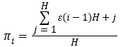 for 1 ≤ I ≤ C
4. Here π1=2/3, π2=1/3 and π3=2/3.
5.
Compute the χ2 statistic: χ2 (obs)= 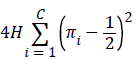
6. 4 × 3 × ((2/3-1/2)2+(1/3-1/2)2+(2/3-1/2)2=0.9996
7. Compute D-value=gammainc (C/2, χ2 (obs)/2) .
8. D-value=gammainc (3/2,0.9996)=0.9168
Runs test
The objective of this test is to find the total number of runs in the sequence, where a run is consecutive ones or zeros. This test decides the count of ones and zeros in the given tag is random in nature.
Test description
Fobs: The total number of zero runs and one runs.
1. λ of ones in the input sequence: λ=Σjzj/m.
2. z=0000010001010111, then m=16 and λ=0.3750
3. Determine whether is frequency test is passed or not: The runs test need not be performed if | λ-1/2| ≥ δ. If the test is not valid, then the D-value is set to 0.00000. δ=2/√ (m) has been already defined in the test code.
4. δ=2/√16≈0.5, then |λ-1/2|=| 0.3750-0.5|=0.125<δ, and the test is not run. The test must be performed.
5. Calculate the test statistic 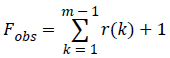 where r (k)=0 if εk=εk+1, and r(k)=1 otherwise.
6. Since z=0000010001010111, then
7. Fobs=(0+0+0+0+0+1+0+0+0+1+0+1+0+1+1+1)+1=7.
8. D-value=erfc (|Fobs-2mλ (1- λ)|/2√2m λ (1- λ)) is computed
9. D=0.6392
Discrete Fourier transform (spectral) test
The objective of this test is to identify the periodic features in the tested sequence that would indicate how much percent it has deviated from randomness.
1. The binary zeros as assigned -1 and binary and ones are assigned +1
2. Discrete Fourier transform (DFT) is applied on X to produce: S=DFT(X).
3. Calculate M = modulus(S´) ≡ |S'|
4. S=√ (log (1/0.05) n) is computed.
5. S=4.5625
6. S0=0.95 n/2 is computed
7. S0 = 7.6
8. Compute M1=number of peaks actually observed. They are less than S.
9. M1=7
10. F=(M1-S0)/√n × 0.05 × 0.95 is computed
11. F=-0.246
12. P value, erfc (|F|/√2) is computed
13. P value=0.24
14. From these four tests it is clear that the authentication tag is random in nature.
Conclusion
This work mainly focussed on mitigating the Primary User Emulation Attack (PUEA) in the physical layer. Authentication is achieved by the addition of special term known as tag. The tag is generated with the aid of Katayapadi algorithm and Bhutasankya algorithm. It is embedded in such a way that there is no drastic change in the performance of the system before and after embedding and it is verified with the aid of matlab simulation. With the available free spectrum medical data has been transmitted from the remote location to the specialist for further consultation which reliefs the senior citizens from travelling a long distance for their health consultation. To gain the benefit of reprogrammability FPGA based implementation is carried out utilizing Altera DE1 board.
References
- Mitola J III. Cognitive radio: An integrated architecture for software defined radio. Royal Institute Technology, Sweden 2000.
- Haykin S. Cognitive radio: Brain empowered wireless communications. IEEE J Selected Areas In Commun 2005; 23: 201-220.
- Kim H, Shin KG. In-band spectrum sensing in cognitive radio networks: energy detection or feature detection. Mobile Comput Networking 2008; 14-25.
- Yuan Q, Tao P, Wang W, Qian R. Cyclostationarity-based spectrum sensing for wideband cognitive radio. Commun Mobile Comput 2009; 107-111.
- Prithiviraj V, Sarankumar B, Kalaiyarasan A, Praveen Chandru P, Nandakumar Singh N. Cyclostationary analysis method of spectrum sensing for cognitive radio. IEEE International Conference on Wireless Communication, Vehicular Technology, Information Theory and Aerospace & Electronic System Technology (wireless VITAE) 2011; 1-5.
- Yucek T, Arslan H. A survey of spectrum sensing algorithms for cognitive radio applications. Commun Surveys Tutorials 2009; 11: 116-130.
- Avila J, Thenmozhi K. Wavelet supersedes FFT in MB-OFDM: An effective cognitive spectrum sensing. J Artificial Intell 2012; 5: 113-121.
- Xiongwei X, Weichao W. Detecting primary user emulation attacks in cognitive radio networks via physical layer network coding. J Ubiquitous Systems Pervasive Networks 2014; 5: 1-8.
- Borle KM, Biao C, Wenliang D. A physical layer authentication scheme for countering primary user emulation attack. IEEE International Conference on Acoustics, Speech and Signal Processing (ICASSP) 2013; 2935-2939.
- Fatty Mustafa S, Maged Hamada I, Ihab Abd El-Wahab A. Secure authentication scheme preventing wormhole attacks in cognitive radio networks. Asian J Comp Sci Inform Technol 2012; 2: 52-55.
- Sharing Fatty M, Salem, Maged HII, Ibrahim I. A primary user authentication scheme for secure cognitive TV spectrum. IJCSI 2012; 9: 157-166.
- Fragkiadakis AG, Tragos EZ, Askoxylakis IG. A survey on security threats and detection techniques in cognitive radio networks. Commun Surveys & Tutorials IEEE 2013; 15: 428-445.
- Alahmadi A, Abdelhakim M, Jian R, Tongtong L. Mitigating primary user emulation attacks in cognitive radio networks using advanced encryption standard. Global Commun Conference 2013; 3329-3334.
- Alahmadi A, Abdelhakim M, Jian R, Tongtong L. Defense against primary user emulation attacks in cognitive radio networks using advanced encryption standard. IEEE Transactions on Information Forensics and Security 2014; 9: 772-781.
- Xi T, Kapil B, Wenliang D, Biao C. Cryptographic link signatures for spectrum usage authentication in cognitive radio. Proceeding of the Fourth ACM Conference on Wireless Network Security 2011; 1-12.
- Bharathi Krisha TM. Vedic mathematics and its spiritual dimensions. Motilal Bansari Publishers 1992.
- Kishan Bhat R, Raajan NR. A new approach to language based encryption using devanagari text. Int J Appl Eng Res 2014; 9: 925-928.
- Haroon R, Farah H, Nandana R. Performance analysis of rice-lognormal channel model for spectrum sensing. International Conference on Electrical Engineering/Electronics Computer Telecommunications and Information Technology 2010; 420-424.
- Abhijit DP, Prashant VI. OFDM system using FFT and LFFT. Int J Adv Res Comp Sci Software Eng 2013; 12: 675-679.
- Abdulrahman AAE. Implementation 7 segment display by educational board-software/hardware interfacing. Int J Eng Res Appl 2012; 2: 748-751.
- Neha RL, Thakare AP. A novel approach for displaying data on LCD directly from PC using FPGA. Int J Emerging Sci Eng 2013; 1: 106-111.
- Benny YZ, Guang G. Randomness properties of stream ciphers for wireless communications. The Sixth International Workshop on Signal Design and its Application in Communications 2013; 107-109.
- Qianying G, Guangyi W. Generation of a chaos-based PN sequence and its quality analysis. International Conference on Communications, Circuits and Systems 2010; 756-759.
- Andrew R, Juan S, James N, Miles S, Elaine B, Stefan L, Mark L, Mark V, David B, Alan H, James D, San V. A statistical test suite for random and pseudorandom number generators for cryptographic applications. Special Publication 2010; 800-822.