Review Article - Materials Science and Nanotechnology (2018) Volume 2, Issue 1
Parametric structural schematic diagram of electroelastic actuator in nanotechnology.
Afonin SM*Department of Intellectual Technical Systems, National Research University of Electronic Technology (MIET), Moscow, Russia
- *Corresponding Author:
- Afonin SM
Department of Intellectual Technical Systems
National Research University of Electronic
Technology (MIET)
Moscow
Russia
E-mail: learner01@mail.ru
Accepted date: February 05, 2018
Citation: Afonin SM. Parametric structural schematic diagram of electroelastic actuator in nanotechnology. Mater Sci Nanotechnol. 2018;2(1):5-9.
DOI: 10.35841/nanotechnology.2.1.5-9
Visit for more related articles at Materials Science and NanotechnologyAbstract
In this work the parametric structural schematic diagram of the electroelastic actuator or the piezoactuator is determined in contrast the electrical equivalent circuit types Cady or Mason for the calculation of the piezoelectric transmitter and receiver, the vibration piezomotor with the mechanical parameters in form the velocity and the pressure. The method of mathematical physics is used. The parametric structural schematic diagram of electroelastic actuator is obtained with the mechanical parameters the displacement and the force. The transfer functions of the electroelastic actuator are determined. The generalized parametric structural schematic diagram, the generalized matrix equation for the electroelastic actuator nano displacement are obtained. The deformations of the electroelastic actuator for the nanotechnology are described by the matrix equation.
Keywords
Electroelastic actuator, Parametric structural schematic diagram, Transfer function, Piezoactuator.
Introduction
The parametric structural schematic diagram of the electroelastic actuator on the piezoelectric, piezomagnetic, electrostriction effects, for example, the piezoactuator is determined in contrast electrical equivalent circuit types Cady or Mason for the calculation of the piezotransmitter and piezoreceiver, the vibration piezomotor with the mechanical parameters in form the velocity and the pressure [1-8]. The parametric structural schematic diagram of the actuator is obtained with the mechanical parameters the displacement and the force. The electroelastic actuator for nanotechnology is used in the scanning tunneling microscopes, the scanning force microscopes, the atomic force microscopes [8-10].
Method
The method of mathematical physics is applied for the solution of the wave equation of the electroelastic actuator for the nanotechnology with using the Laplace transform for the construction the parametric structural schematic diagram of electroelastic actuator [11-16].
As the result of the joint solution of the wave equation of the actuator with the Laplace transform, the equation of the electroelasticity, the boundary conditions on the two loaded working surfaces of the actuator, we obtain the corresponding structural-parametric model and the parametric structural schematic diagram of electroelastic actuator.
Results and Discussion
The parametric structural schematic diagram and the matrix transfer functions of the electroelastic actuator for the nanotechnology are obtained from the structural-parametric model of the electroelastic actuator with the mechanical parameters the displacement and the force. The structural diagrams of the voltage-controlled or current-controlled piezoactuator are determined from the generalized structuralparametric model of the electroelastic actuator [17,18].
Generalized parametric structural schematic diagram
Let us consider the generalized equation of the electroelasticity [8,11,18] in the form:

where  the relative displacement along
axis i of the cross section of the piezoactuator or the piezoplate,
the relative displacement along
axis i of the cross section of the piezoactuator or the piezoplate,  is the control parameter E for the voltage control,
D for the current control along axis m, Tj is the mechanical
stress along axis j, dmi is the coefficient of electroelasticity, for
example, piezomodule,
is the control parameter E for the voltage control,
D for the current control along axis m, Tj is the mechanical
stress along axis j, dmi is the coefficient of electroelasticity, for
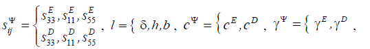
example, piezomodule,  is the elastic compliance for control
parameter Ψ = const , indexes
is the elastic compliance for control
parameter Ψ = const , indexes 
The main size is determined us the working length  for the electroelastic actuator or the piezoactuator in
form the thickness, the height and the width for the longitudinal,
transverse and shift the piezo effect.
for the electroelastic actuator or the piezoactuator in
form the thickness, the height and the width for the longitudinal,
transverse and shift the piezo effect.
For the construction the parametric structural schematic diagram of electroelastic actuator in nanotechnology is used the wave equation [8,11,18] for the wave propagation in a long line with damping but without distortions. With using Laplace transform is obtained the linear ordinary second-order differential equation with the parameter p. Correspondingly the original problem for the partial differential equation of hyperbolic type using the Laplace transform is reduced to the simpler problem [8,11,12] for the linear ordinary differential equation
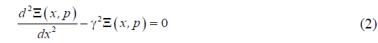
with its solution
where  is the Laplace transform of the displacement
of section of the actuator.
is the Laplace transform of the displacement
of section of the actuator. 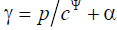 is the propagation
coefficient, cΨ is the sound speed for Ψ = const , α is the
damping coefficient, C and B are constants.
is the propagation
coefficient, cΨ is the sound speed for Ψ = const , α is the
damping coefficient, C and B are constants.
The generalized structural-parametric model and the generalized parametric structural schematic diagram of the electroelastic actuator for nanotechnology on Figure 1 are determined, using equations (1) and (2), the boundary conditions on loaded faces and the strains along the axes, in the following form

Figure 1. Generalized parametric structural schematic diagram of electroelastic actuator in nanotechnology.
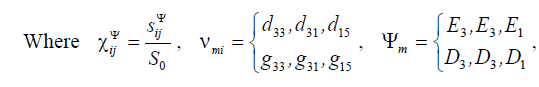
 is the coefficient of the electroelasticity, for example,
 is the piezomodule for the voltage-controlled piezoactuator,
  is the piezomodule for the current-controlled piezoactuator,
  is the cross section area and
  M are the displaced mass
on the faces of the electroelastic actuator, F 1 (p) , F1(p) and F1(p), F2 (p) are the Laplace transform of the displacements and the forces on the faces of the electroelastic actuator, Ψm is the
control parameter of the electroelastic actuator.
M are the displaced mass
on the faces of the electroelastic actuator, F 1 (p) , F1(p) and F1(p), F2 (p) are the Laplace transform of the displacements and the forces on the faces of the electroelastic actuator, Ψm is the
control parameter of the electroelastic actuator.
The matrix state equations [2,11,14] for the piezoelectric effect have the form:
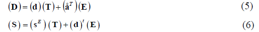
where the first equation describes the direct piezoeffect, the second equation presents the inverse piezoeffect, (D) is the column-matrix of the electric induction along the coordinate axes, (S) is the column-matrix of the relative deformations, (T) is the column-matrix of the mechanical stresses, (E) is the column-matrix of the electric field strength along the coordinate axes, (d)t is the transposed matrix of the piezoelectric modules, (sE ) is the elastic compliance matrix, (εT) (åT ) is the matrix of dielectric constants
The deformation of the piezoactuator corresponds to its stressed state. If the mechanical stress S are created in the piezoelement, the deformations S are formed in it [8,11].
There are the six stress components T1, T2, T3, T4, T5, T6. The components T3 − T3 are defined to extension-compression stresses, the components T4−T6 are related to shear stresses.
Let us consider the transverse piezoelectric effect in the piezoactuator shown in Figure 2. The equation of the inverse transverse piezoeffect [8,11].

Figure 2. Piezoactuator for the transverse piezoelectric effect.

where  is the relative displacement of the
cross section of the piezoactuator along axis
is the relative displacement of the
cross section of the piezoactuator along axis  is the
piezoelectric module for the transverse piezoeffect,
is the
piezoelectric module for the transverse piezoeffect,  is the
elastic compliance for E = const along axis 1, T1 is the stress
along axis 1.
is the
elastic compliance for E = const along axis 1, T1 is the stress
along axis 1.
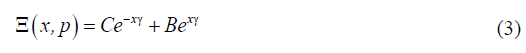
The solution of the linear ordinary second-order differential equation with the parameter p (2) can be written as (3) and subject to the conditions
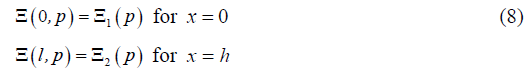
Therefore the constants C and B for the solution we obtain in the following form:

Then, the solution (3) can be written as:

The equations of forces acting on the faces of the piezoactuator has the form:
where 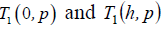 are determined from the equation
of the inverse transverse piezoeffect.
are determined from the equation
of the inverse transverse piezoeffect.
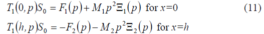
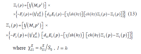
Therefore we obtain the system of the equations for the mechanical stresses at the faces of the piezoactuator for the transverse piezoeffect in the form:
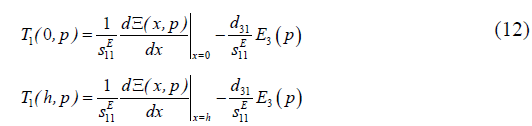
The set of equations (12) for mechanical stresses in piezoactuator yields the following set of equations describing the structural parametric model and parametric structural schematic diagram of the voltage-controlled piezoactuator for the transverse piezoelectric effect on Figure 3.

Figure 3. Parametric structural schematic diagram of voltagecontrolled piezoactuator for transverse piezoelectric effect.
The parametric structural schematic diagrams of the voltagecontrolled or current-controlled piezoactuator for the transverse, longitudinal, shift piezoelectric effects are determined from the generalized structural-parametric model of the electroelastic actuator.
Matrix equation of displacements
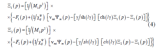
From generalized structural-parametric model of the electroelastic actuator, taking into account the generalized equation of the electroelasticity, wave equation and the equation of the forces on its faces, we obtain the transfer functions of the electroelastic actuator.
Correspondingly the Laplace transforms of displacements for two faces of the electroelastic actuator are dependent from the Laplace transforms of the general parameter of control and forces on two faces. Matrix equation of the Laplace transforms of the displacements with the matrix transfer functions of the electroelastic actuator is obtained [8,14,18] in the form

Let us consider the displacements the faces of the voltagecontrolled
the piezoactuator for the transverse piezoeffect  with the output parameter displacement.
In matrix equation (14) the transfer functions of the voltagecontrolled the piezoactuator for the transverse piezoeffect can be written in the following form:
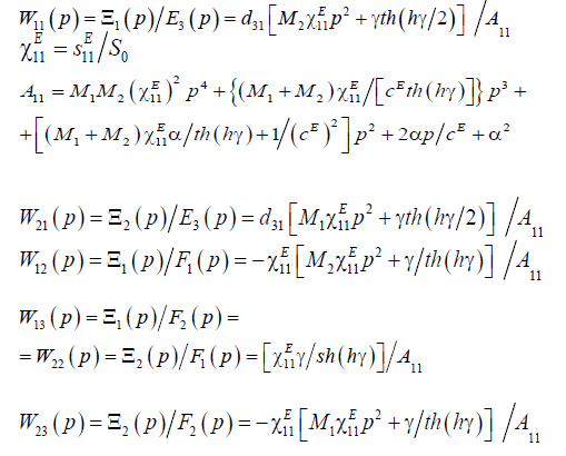
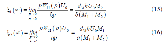
The static displacements of the faces for the voltagecontrolled
the piezoactuator for the transverse piezoeffect are
obtained from (14) at  in the form
For the voltage-controlled the piezoactuator from PZT
under the transverse piezoeffect at 
 kg and
 kg the static displacements of the faces the
piezoactuator are determined
kg the static displacements of the faces the
piezoactuator are determined 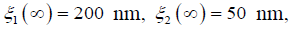
The transfer function of the voltage-controlled transverse
piezoactuator is obtained from (14) for elastic-inertial load
at  and the approximation the hyperbolic
cotangent by two terms of the power series in the form:
and the approximation the hyperbolic
cotangent by two terms of the power series in the form:
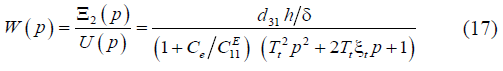

where U ( p) is the Laplace transform of the voltage, Tt is the time constant and ξt is the damping coefficient of the piezoactuator.
Therefore the expression for the transient response of the voltage-controlled transverse piezoactuator is determined in the following form:

where  is the steady-state value of displacement for the
voltage-controlled piezoactuator,
is the steady-state value of displacement for the
voltage-controlled piezoactuator,  is the amplitude of the
voltage in the steady-state. For
is the amplitude of the
voltage in the steady-state. For 
 N/m,
N/m, we obtain values the steady-state value
of displacement and the time constant of the actuator
we obtain values the steady-state value
of displacement and the time constant of the actuator  nm,
nm, 
The matrix transfer functions of the actuator are determined for control systems with the electroelastic actuator in the nanotechnology.
In this work the generalized parametric structural schematic diagram and generalized structural-parametric model of the electroelastic actuator are obtained. From generalized structuralparametric model of the electroelastic actuator after algebraic transformations the transfer functions of the electroelastic actuator are determined.
The parametric structural schematic diagrams, the structuralparametric models of the piezoactuator for the transverse, longitudinal, shift piezoelectric effects are determined from the generalized structural-parametric model of the electroelastic actuator for nanotechnology.
Conclusion
For nanotechnology the generalized parametric structural schematic diagram and the generalized structural-parametric model of the electroelastic actuator are constructed with the mechanical parameters the displacement and the force.
The parametric structural schematic diagrams of the piezoactuator for the transverse, longitudinal, shift piezoelectric effects are determined.
The matrix transfer functions of the electroelastic actuator are determined for control systems in the nanotechnology.
References
- Schultz J, Ueda J, Asada H. Cellular actuators. Oxford: Butterworth-Heinemann Publisher. 2017:382.
- Afonin SM. Absolute stability conditions for a system controlling the deformation of an elecromagnetoelastic transducer. Doklady mathematics. 2006;74(3):943-48.
- Zhou S, Yao Z. Design and optimization of a modal-independent linear ultrasonic motor. IEEE transaction on ultrasonics, ferroelectrics, and frequency control. 2014;61(3):535-46.
- Przybylski J. Static and dynamic analysis of a flextensional transducer with an axial piezoelectric actuation. Engineering Structures. 2015;84:140-51.
- Ueda J, Secord T, Asada HH. Large effective-strain piezoelectric actuators using nested cellular architecture with exponential strain amplification mechanisms. IEEE/ASME transactions on mechatronics. 2010;15(5):770-82.
- Karpelson M, Wei GY, Wood RJ. Driving high voltage piezoelectric actuators in microrobotic applications. Sensors and actuators A: Physical. 2012;176:78-89.
- Afonin SM. Block diagrams of a multilayer piezoelectric motor for nano- and micro-displacements based on the transverse piezoeffect. J Comput Syst Sci Int. 2015;54(3):424-39.
- Afonin SM. Structural parametric model of a piezoelectric nanodisplacement transduser. Doklady Physics. 2008;53(3):137-43.
- Afonin SM. Solution of the wave equation for the control of an elecromagnetoelastic transducer. Doklady Mathematics. 2006;73(2):307-13.
- Cady WG. Piezoelectricity: An introduction to the theory and applications of electromechancial phenomena in crystals. New York, London: McGraw-Hill Book Company. 1946;806.
- Physical acoustics: Principles and methods. Part A. Methods and devices. Ed.: Mason W. New York: Academic Press. 1964;1:515.
- Zwillinger D. Handbook of differential equations. Boston: Academic Press. 1989;673.
- Afonin SM. Structural-parametric model and transfer functions of electroelastic actuator for nano- and micro-displacement. Chapter 9 in Piezoelectrics and nanomaterials: Fundamentals, developments and applications. Ed. Parinov IA. New York: Nova Science. 2015;225-42.
- Afonin SM. A structural-parametric model of electroelastic actuator for nano- and microdisplacement of mechatronic system. Chapter 8 in Advances in nanotechnology. Volume 19. Eds. Bartul Z, Trenor J. New York: Nova Science. 2017;259-84.
- Afonin SM. Nano- and micro-scale piezomotors. Russian engineering research. 2012;32(7-8):519-22.
- Afonin SM. Elastic compliances and mechanical and adjusting characteristics of composite piezoelectric transducers. Mech Solids. 2007;42(1):43-9.
- Afonin SM. Stability of strain control systems of nano-and microdisplacement piezotransducers. Mech Solids. 2014;49(2):196-207.
- Afonin SM. Structural-parametric model electromagnetoelastic actuator nanodisplacement for mechatronics. Int J Phys. 2017;5(1):9-15.