Research Article - Biomedical Research (2018) Volume 29, Issue 9
Mathematical modeling and control of lower extremity exoskeleton
Alper K Tanyildizi, Oğuz Yakut and Beyda Tasar*
Department of Mechatronic Engineering, Faculty of Engineering, Firat University, Elazig, Turkey
- *Corresponding Author:
- Beyda Tasar
Department of Mechatronic Engineering
Faculty of Engineering, Firat University, Elazig, Turkey
Accepted date: March 21, 2018
DOI: 10.4066/biomedicalresearch.29-18-509
Visit for more related articles at Biomedical ResearchAbstract
In this study, a new active control strategy of 2 degrees of freedom exoskeleton robot was realized. Firstly, a double-pendulum mechanism is used to demonstrate the human amplifier robot which follows and assists the healthy human low body movements. Secondly, mathematical model of this system is created and the PID control method was applied to the robot. Feedback information for controller was supported via the pressure forces sensors, which located at the front and rear of the leg between the human leg and the double-pendulum links. The simulation results are obtained for three motion scenarios and interpreted graphically. According to the graphically obtained results, it is obvious that the robot can successfully follow the human leg under different load conditions and successfully carry these loads without transferring them to the leg muscles. The proposed TDB model appears to be a suitable model for describing the motion of the exoskeleton robot.
Keywords
Modeling of dynamic systems, Motion control, Exoskeleton, Human-robot interaction, Calculation of interaction force
Introduction
In recent years, wearable robots have been quite popular among research and projects in the field of robotics. Wearable robots are defined as robotic devices designed with joints and links to match the skeletal-muscle system and movement function of the human body when operator worn it [1].
As a result of the transferring user's motivation desire to the robot via cognitive interaction network, the exoskeleton robot can support the movement activity of human and increase the physical strength (load carrying capacity, working time, etc.). Initially they were designed for military and rehabilitation applications [2]. In recent years, many different exoskeleton robots have been designed by researchers for rehabilitation and military purposes [3-6]. The recognition of the human motion desire is very important for the efficient control of the exoskeleton robot used with the assistant of human motion. Control algorithms are classified under three headings in the literature according to method of collecting data for human-robot interaction. These methods are signals recorded from only human body, signals recorded only from the exoskeleton and Interaction force value measured. In the first method, it is the principle that the direct biological signals are recorded from the human directly and then human movement desire is determine via these signals. For this reason, information and time loss are very low in this method compared to the other two methods, and it is possible to recognize of human motion desire with a high accuracy [1].
There are two types of biological signals, which are used for human robot ınteraction studies. These are: the skin surface Electromyography (EMG) and the electroencephalogram (EEG) [7-12]. These signal based control strategy have been also used to assist older or paraplegic person during daily activity. Biomedical signal recorder devices are not useful for military exoskeleton robots. Because of biomedical sensors are effect environmental factors, vibration and impact are affected.
The second method is a model-based control strategy that not collects any biological signals from the human body [13]. As it is known, this structure cannot be modelled without certain omissions. For example, the leg links are rigid and the center of gravity is at the exact midpoint of the link. But such a model does not exactly reflect reality and makes control difficult.
The third control strategy used in this study is to design the human-robot cognitive interaction via the interaction forces measured between the user and the exoskeleton. Some researchers measure this interaction force from the point of connection between the user and the robot, while others calculate the deformation rate of the elastic material placed in the robot link [10,14]. A new distribute method are used in order to measure the pressure interaction between human and robot [15]. A healthy person worn a lower extremity exoskeleton robot named LOPES and the researchers tested their purposed method. The results showed that the interaction force between human and exoskeleton robot can be accurately calculated. Furthermore, this design is very comfort and safety for users and calculates interaction force in real time. The force based interaction method was used for HAL-5 [16]. Position of the center of gravity was calculated via Floor Reaction Force (FRF) sensor to estimate the human-robot interaction. In a force-sensing design was used to extract information about physical interaction [17]. And also Xinyi et al. used neural network control [18]; Fliess et al. were used PID controllers for exoskeleton [19,20]. Ahmed et al. were used sliding mode controller for model free robot [21]. In this study, a force measurement approach was taken as a basis and a mathematical model of the system was established.
Overview and Highlight of Study
Figure 1 shows an overview of this study. In this study, it is decided that the best model that can fulfil basic leg movements is the double pendulum. For this reason, the fixed joint is represented by the human hip; the moving joint is represented by the knee.

Figure 1: Overview of the study.
The reaction forces between the robot and the human leg were taken as reference and the movement control of robot was intended to be realized in accordance with this reference value. Whereas other studies which are used IMU sensor, pressure sensor at the sole, gyroscope etc. in this study two force sensors will be placed between the leg and the robot. So the data given by the force sensor will be used as the errors between the leg and the robot. To demonstrate this leg and robot a twin double-pendulum (TDP) is used.
Conceptual Design of Exoskeleton Robot
In this study, the reaction forces between the robot limbs and the human knee were taken as reference and the movement control of robot was intended to be realized in accordance with this reference value.
The force measuring sensors of the designed robot are positioned on the front and rear of the leg. Thus, when the leg starts to move, a reaction force will be generated in these sensors as the drivers of the robot will remain stationary. When attempting to move the human leg forward, the force sensors positioned on the front face will be activated. With a speed determined according to the magnitude of the measured reaction force, the driving units will try to move the robot limb forward. The drivers will continue to move the robot until the measured forces on the front face sensors reach zero. Likewise, if the force sensors on the rear side feel any pressure, the robot will move backwards. Motion trajectory is obtained according to an algorithm as Table 1.
| Algorithm: Obtain of motion trajectory according to force sensor |
| I_Force Initial force sensor value when leg not move |
| N_Force measurement value when leg move |
| reference Initial position When Force=0 |
| while true |
| Interaction_Force=N_Force-I_Force; |
| if (Interaction_Force)>0 |
| reference=reference++; |
| else |
| reference=reference--; |
| endif |
| endwhile |
Table 1: Obtain of motion trajectory according to force sensor.
Mathematical Model of Human Leg and Human Amplifier Robot
There is a need for a mathematical model that reveals the interaction between human and robot. The kinematic diagram reflecting the physical model of human leg and exoskeleton is shown in Figure 2. The limb angles are denoted by θi, the masses are by mi, the lengths are by li, and centers of gravity are by Gi. The spring elements of k1 and k2 in the model represent force sensors that measure the reaction forces. All angles were referenced to the vertical axis.

Figure 2: Model of the robot and human limb.
The Lagrange equations method is used when a mathematical model is constructed [22].
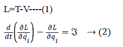
Where T denotes the kinetic and V the potential energy, and ![]() is the moment that must be applied to the joint.
is the moment that must be applied to the joint.
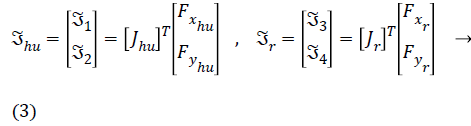
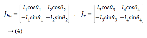
The Jhu, in the Equation 3, shows the Jacobian matrix of human leg, Fxhu is the force applied to the human heel in the x direction, and the Fyhu is the force applied to the human heel in the y direction. The Jacobean matrix of human leg and robot limbs are as follows:
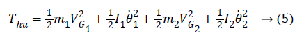
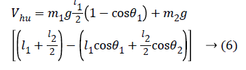
The kinetic and potential energy expressions for human leg can be written as follows:
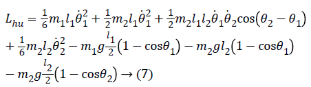
Lagrange function can be obtained from here as follows:
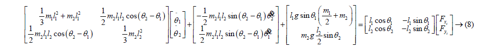
The obtained Lagrange function can be written in Equation (2) and written in the form of a matrix as follows after the necessary mathematical operations.
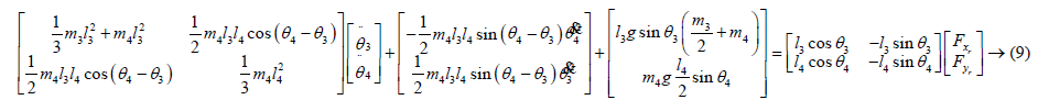
Similarly, these operations can also be performed for the robot's limbs and the following expressions can be obtained.
PID Control System Implementation
The classic PID control method is one of the most preferred feedback control methods in control systems [23,24]. Genetic algorithm technique was used for optimum values of control parameters [25-27]. The coefficients of the PID control parameters obtained are given in Table 2.
| PID controller parameters | KP | KD | KI |
|---|---|---|---|
| Hip actuator | 15 | 0.01 | 6 |
| Knee actuator | 5 | 0.012 | 5 |
Table 2: PID control parameters for hip and knee joints of exoskeleton.
Figure 3 shows the block diagram of the representation that the coefficients of the controller are optimized by the genetic algorithm technique [28-30]. Sum of the squares of the errors was chosen as fitness function for genetic algorithm.

Figure 3: Block diagram of the optimization of the control parameters.
Numerical Simulations and Interpretations
The main goal of this study is to enable the robot to follow the leg movements in different loads and to carry these loads without leaving the feeling of the loads on the leg. To reveal this achievement, the control torques that should be applied to the joints for the movement of the human leg in the simulations is also obtained graphically.
In numerical simulations are obtained for 3 different situations. Our exoskeleton robot model designed for military purpose; for this reason it was simulated to analyze the movements of soldiers’ troops for three separate load cases. These scenarios are:
1. Take out the trooper bag and make a discovery while unloaded.
2. In case of daily exercise; it carries a bag of 10 kg which is full of food and light munitions (a load of 100 N was applied).
3. In case of actual exercise; it carries a bag of 50 kg which is full of arsenal-equipped and food (a load of 500 N was applied).
For these motions, equations are solved using the fourth order Runge Kutta method in the MATLAB package program. Kinematic parameters, spring and damping parameters and initial position of human and robot joints were presented Tables 3-5 respectively.
| Human femoral | Human tibial | Robot femoral | Robot tibial | |
|---|---|---|---|---|
| Mass (kg) | 8 kg | 4 kg | 1 kg | 1 kg |
| Length (m) | 0.45 m | 0.43 m | 0.45 m | 0.43 m |
Table 3: Kinematic parameters for the numerical solution.
| k1 (1. Spring coefficient) | 5 × 10³ N/m | c1 (1. Damping coefficient) | 0.1 N.s/m |
| k2 (2. Spring coefficient) | 5 × 10³ N/m | c2 (2. Damping coefficient) | 0.1 N.s/m |
Table 4: Spring and damping parameters.
| Human link | Robot link | |||
|---|---|---|---|---|
| Joint 1 | Joint 2 | Joint 3 | Joint 4 | |
| Position (θi0) | 450 | -450 | 450 | -450 |
| Angular velocity (θi0) | 0 m/s | 0 m/s | 0 m/s | 0 m/s |
Table 5: Initial conditions of joints for the simulation.
The graphics in the Figures 4 and 5 show the change in position of the leg and robot limbs with respect to time in the context of the control applied according to different load cases. According to the obtained graphical results, the robot was able to follow leg movements very successfully.

Figure 4: Positions of the human hip and knee joints for F=0 N, F=100 N and F=500 N.

Figure 5: Positions of the robot hip and knee joints for F=0 N, F=100 N and F=500 N.
Figure 6 (a) shows the angular error graph of the hip joint (θ1-θ3). Figure 6 (b) shows a graph of angular errors in the knee joint (θ2-θ4). Figures 7 (a) and (b) show the variation of these reaction forces between leg and robot.

Figure 6: (a) Error in the hip joint; (b) Error in the knee joint.

Figure 7: (a) First spring force; (b) Second spring force.
Figures 8 (a) and (b) show the control signal that should be applied to the hip joint of the human and robot leg. As it can be seen, there is no extra strain in the joints of the human leg despite the different loads applied.

Figure 8: (a) Control signal of the human hip; (b) Control signal of the robot hip.
Figures 9 (a) and (b) show the control signals that should be applied to the knee joint of the human and robot leg. Particularly, as it is understood from the control signal graphs of the knee joint, the robot leg helps to lessen the load on the human knee.

Figure 9: (a) Control signal of the human knee; (b) Control signal of the robot knee.
Conclusion
This paper presents the conceptual design and active control strategy of a wearable lower limb exoskeleton developed to augment healthy individuals such as soldiers. Human-exoskeleton robot interaction was supported via force sensors. Force sensor was placed between the leg and the robot limb to provide interact between the human and exoskeleton robot.
According to the graphically obtained results, it is obvious that the robot can successfully follow the human leg under different load conditions and successfully carry these loads without transferring them to the leg muscles. System for all load condition was reached steady state position in 0.426 s. steady state time and zero degree steady state error values via PID controller. The proposed TDB model appears to be a suitable model for describing the motion of the exoskeleton robot.
Acknowledgement
The subject of this article, which is Alper TANYILDIZI’s doctoral thesis, was supported by FUBAP, Project number MF-17.12.
Conflict of Interest
Oguz Yakut, Alper K. Tanyildizi and Beyda Tasar declare that she has no conflict of interest.
References
- Ahmed S, Wang H, Tian Y. Model-free based adaptive nonsingular fast terminal sliding mode control with time-delay estimation for a 12 dof lower limb rehabilitation exoskeleton. Advances in Engineering Software 2018; 119: 38-47.
- Astrom KJ, Hagglund T. PID controllers: theory, design and tuning. Instrument Society of America 1998; 343.
- Dollar AM, Herr H. Lower extremity exoskeletons and active orthoses: challenges and state of the art. IEEE Trans Robot 2008; 24: 144-158.
- De Rossi M. Sensing pressure distribution on a lower-limb exoskeleton physical human-machine interface. Sensors 2011; 11: 207-227.
- Del-Ama AJ, Moreno JC, Gil-Agudo A, De-los-Reyes A, Pons JL. Online assessment of human-robot interaction for hybrid control of walking. Sensors 2012; 12: 215-225.
- Fleischer C, Wege A, Kondak K, Hommel G. Application of EMG signals for controlling exoskeleton robots. Biomed Tech Biomed Eng 2006; 51: 314-319.
- Fleischer C, Reinicke C, Hummel G. Predicting the intended motion with EMG signals for an exoskeleton orthosis controller. In Proc IEEE Int Conf Robot Auton Syst 2005; 2029-2034.
- Fleischer C, Hommel G. Embedded control system for a powered leg exoskeleton. Embedded Systems-Modeling, Technology and Applications, Springer 2006.
- Fliess M, Join C. Model-free control and intelligent PID controllers: towards a possible trivialization of nonlinear control. Syst Identif 2009; 15: 1531-1550.
- Fliess M, Join C. Model-free control. Int J Control Taylor 2013; 86: 2228.
- Gupta MK, Bansal K, Singh AK. Mass and length dependent chaotic behavior of a double pendulum. Third International Conference on Advances in Control and Optimization of Dynamical Systems 2014.
- Goldberg DE. Genetic algorithms in search, optimization and machine learning. Addison-Wesley Publishing Company Inc., USA 1989.
- Haupt Randly L, Haupt Sue E. Practical genetic algorithms. A Willey-Interscience Publication, USA 1998.
- Huo W, Mohammed S, Moreno JC, Amirat Y. Lower limb wearable robots for assistance and rehabilitation: a state of the art. IEEE Systems J 2014; 99: 1-14.
- Kawamoto H, Sankai Y. Power assist method based on phase sequence and muscle force condition for HAL. Adv Robot 2005; 19: 717-734.
- Kazerooni H, Steger R. The Berkeley lower extremity exoskeletons. Trans ASME J Dynam Syst Meas Control 2006; 128: 14-25.
- Kim H, Shin YJ, Kim J. Design and locomotion control of a hydraulic lower extremity exoskeleton for mobility augmentation. Mechatronics 2017; 46: 32-45.
- Lew E, Chavarriaga R, Silvoni S, Millán JDR. Detection of selfpaced reaching movement intention from EEG signals. Front Neuroeng 2010; 5: 1-17.
- Man KF, Tang KS, Kwong S. Genetic algorithms: concepts and applications. IEEE Transactions on Industrial Electronics 1996; 43: 519-534.
- Marchal-Crespo L, Reinkensmeyer DJ. Review of control strategies for robotic movement training after neurologic injury. J NeuroEng Rehab 2009; 6: 1-15.
- Mohammed S, Amirat Y, Rifai H. Lower-limb movement assistance through wearable robots: State of the art and challenges. J Adv Robotics 2012; 26: 1-22.
- Pons JL. Wearable robots: Biomechatronic exoskeletons. Wiley, New York, NY, USA 2008.
- Pons JL. Rehabilitation exoskeletal robotics. IEEE Eng Med Biol Mag 2010; 29: 57-63.
- Suzuki K, Mito G, Kawamoto H, Hasegawa Y, Sankai Y. Intention-based walking support for paraplegia patients with robot suit HAL. Adv Robot 2007; 21: 1441-1469.
- Taguchi H, Araki M. Two degree of freedom PID controllers. Proceedings of the IFAC Workshop on Digital Control: Past, Present and Future of PID Control. Elsevier 2007; 91-96.
- Vukobratovic M, Potkonjak V, Tzafestas S. Human and humanoid dynamics-from the past to the future. J Intelligent and Robotic Syst 2004; 41: 65-84.
- Valiente A. Design of a quasi-passive parallel leg exoskeleton to augment load carrying for walking. Massachusetts Institute Technology, Cambridge, UK 2005.
- Wang Y, Makeig S. Predicting intended movement direction using EEG from human posterior parietal cortex. In Proc 5th Int Conf Found Augmented Cognition Neuroergonomics Oper Neurosci 2009; 5638: 437-446.
- Yu S, Wang Z, Kewang Z. Sequential time-dependent reliability analysis for the lower extremity exoskeleton under uncertainty. Reliability Eng System Safety 2018; 170: 45-52.
- Xinyi Z, Haoping W, Yang T, Laurent P, Wang X. Model-free based neural network control with time-delay estimation for lower extremity exoskeleton. Neurocomputing 2018; 272: 178-188.