Research Article - Biomedical Research (2017) Volume 28, Issue 19
A switching based PID technique for blood glucose control
Muhammad Hamayun Qammar Kayani, Kainat Naeem Malik, Shaban Ahmad, Ali Khaqan*, Sana Shuja, Qadeer-ul-Hasan, Shahzad A. Malik and Raja Ali Riaz
COMSATS Institute of Information Technology Department of Electrical Engineering Chak Shahzad Park Road, Islamabad, Pakistan
- *Corresponding Author:
- Ali Khaqan
COMSATS Institute of Information Technology-Wah Campus
Islamabad, Pakistan
Accepted date: September 27, 2017
Abstract
Automation of insulin infusion by closed loop control method is the center of attention for many researchers for the last few decades. The main idea behind the insulin automation is artificial pancreas for the accurate measurements of glucose level so the key role is played by the control strategy used to design control algorithm. This paper proposes a Proportional Integral Derivative (PID) algorithm based on switching technique to control and maintain the glucose level. We have used mathematical models like Havorka model and Meal Simulation model to deal with the dynamics of insulin and glucagon. Simulation results show that the PID control algorithm performs well in many situations such as insulin sensitivity. To check the effectiveness of the control scheme the glucose profile of patient is generated by using MATLAB. The presented control techniques found to be better as compared to traditional method of insulin injection and are helpful in reducing the risks of hypoglycemia.
Keywords
Automated insulin infusion, Artificial pancreas, PID, Root locus, Havorka model, Meal simulation model
Introduction
Diabetes is an incurable disease affecting number of people throughout the world. According to a survey by 2034, the number of diabetic patients will increase up to 44.1 million. Such circumstances are the reason of motivation of control engineers to present effective and advanced solution [1,2]. In diabetes control, Pancreas plays an important role in maintaining the blood glucose level and is responsible for the production of hormones and enzymes which help in breaking down of food. In pancreas there are α-cells which are responsible for the production of glucagon while β-cells are responsible for the production of insulin. The demolishing of α-cells and β-cells results in hypoglycemia and hyperglycemia respectively [3,4].
In order to avoid the elongation of hyperglycemic issues the victim is dependent on insulin infusion along with the problem of self-monitoring as the patient has to monitor his/her blood glucose level throughout the life. Diabetes requires selfmonitoring and management which is neither reliable nor provides an effective control of blood glucose. Thus, the issue of controlling the blood glucose level and the automation of insulin infusion in diabetic patients is an enduring problem.
The Artificial Pancreas plays an important role in the automation of insulin delivery. It comprises of a control strategy for closed loop system, a hypodermic infusion pump and glucose monitoring system. A number of control techniques including Model Predictive Control (MPC) [5,6], Linear Parameter Varying (LPV) [7], H∞ Control [8,9] have been tested in clinical trials.
We will not discuss these techniques in detail as they have been reviewed in many survey articles recently [10,11]. The PID control strategy has been used widely in industrial control systems as well as in bio-medical field because Proportional Integral Derivative (PID) controller is irresistible for controlling blood glucose as it replicates the responses of first and second phase which are used to secrete insulin by β-cells in pancreas against continuously monitored glucose.
In an artificial pancreas glucose levels of the patients are continuously being monitored and insulin is being injected according to need of patient apart from using rupture techniques for blood glucose monitoring but due to interpatient changeability and sensing delays a tuning method is necessary, considering specific characteristics of patients to achieve better performance in close loop [12]. Insulin feedback loop is used to keep blood glucose level in normal range by injecting estimated amount of insulin in patient to achieve safe control of hypoglycemia.
In this paper an improved blood glucose control technique has been developed using PID controller and effects of Proportional, Derivative and Integral controllers are discussed. This paper is organized as follows: The Physiological model is described in section II, Controller design is presented in section III, section IV and V comprises of Simulation results and discussion. Finally the conclusion is drawn in section VI.
Physiological Model
Several physiological models are used to describe insulin and glucose dynamics [13-15]. In real patients the parameters of models under consideration cannot be estimated as they have their own physiological importance. It is difficult to understand such complex models therefore for research purposes it is necessary to convert those complex models into low order models as they are easy to understand as compared to complex ones. Therefore using black box approach a low order model is identified by considering three different glucose concentrations 90, 120 and 150 mg/dl. By the frequency response of these concentrations we are able to get three linear models for every patient [16].
Basal insulin (Ib) which is responsible for particular glucose level at steady state is measured. After obtaining, basal insulin is added with sinusoidal insulin. By setting the sampling time at 10 min, this signal is injected and glucose variation is captured. An algorithm of Subspace identification was used to obtain a third order system [17,18]. By considering these models a discrete time transfer function is defined as described in equation (1) shown below,
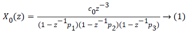
Where P1=0.965, P2=0.95 and P3=0.93 are the poles of the system and C0=0.932. In order to limit traditional nature of the controller, an individualized transfer function is obtained using 1800 rule [14]. 1800 rules are used for measuring value of insulin needed. There is always need to correct for hypoglycemic excursions despite optimal basal therapy.
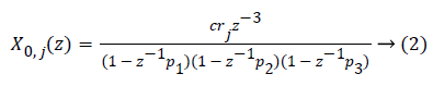
Where rj=1800/TDIj. TDIj is the total daily insulin of patient with index j and c is a constant which can be obtained as,
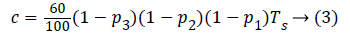
Ts represents the sampling time of the system. Thus is adjusted to each patient and by using individualized transfer function traditionalism of controller can be avoided.
Controller Design
In order to control diabetes, several PID control techniques were developed which are explained in many research articles and survey papers. Most of these techniques are based on simulations and some are applied practically on animals & humans. A lot of research has been done using only PD controllers whereas integral action is ignored as it is responsible for overdosing and low blood sugar levels. Some researchers also used integral action to adjust sudden changes in patients (e.g: Insulin sensitivity).
The rate at which insulin is injected by pump into hypodermic tissues is calculated by PID controller. The noise effect reduction is achieved by filtering the glucose concentration with standard first order filter [19]. PID technique for diabetes demands high proportional and derivative action as compared to integral action. This can be achieved by putting upper and lower limits on the integral term which makes the effect of integral action negligible as compared to derivative and proportional terms. Integral action is necessary as it is responsible to eliminate steady state error when insulin sensitivity changes. Detail analysis and implementation of PID strategies can be found in figures 1 and 2 [20].

Figure 1: Block diagram of closed loop using PID controller.

Figure 2: Block diagram of PID with IFL.
In order to design a control strategy system’s parameters are given i.e. natural frequency ωn=0.02 and damping ratio ξ=0.707. The PID controller is designed to remove the difference between set point value of glucose and present value of glucose. Firstly Proportional action of the controller is tuned and by the results of this action, Kp is determined along with Controller derivative time constant TD. The derivative and integral gain was determined by considering different meal challenges and by finding the best response of the controller against these meal challenges. Finally all the gains of PID are re-evaluated to ensure that after meal hypoglycemia did not happen. The finely tuned PID controller deals with hypoglycemia and hyperglycemia when switch at proper interval. Each gain of PID controller is tuned to minimize,
• Integral Absolute error.
• High glucose values.
• Low glucose values.
The blood glucose controller consists of two parts:
• A. PID controller
• B. Insulin feed-back loop (IFL)
The block diagram of overall closed loop system with PID controller is shown below:
In the block diagram ‘r’ is the reference input and ‘e’ is the error signal which is calculated by subtracting reference input level from present glucose level of patient under consideration. This error signal is then feed to controller block i.e. PID. The controller block sense the error signal and feed patient with required amount of insulin through insulin feedback loop IFL. A.
PID controller
The controller which is generally used in industrial processes is PID controller. Its transient response is very fast and having large power to overcome the steady state error. The three control actions of the PID controller are proportional, integral and derivative. In PID, the system’s output is feed backed to input through closed loop. If the output of the system have some difference between the reference point then PID controller modify the input according to the difference in the reference point and output.
The PID controller consists of three parameters which have different actions and functions. The output of the system due to proportional parameter of controller depends on the present change in the error. The system’s output due to the integral parameter depends on the past error and the output due to the derivative parameter depends on the future error. By using all these control actions i.e. PID we get a good performance control technique. In order to get the desired output of the system we adjust the values of these three parameters. Proportional Integral (PI), Proportional Derivative (PD) and Proportional Integral Derivative (PID) are the combination of these three parameters and explained in equation (4) [21].
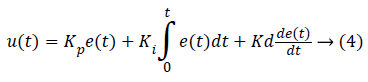
Where u (t) represents the overall control function of PID controller and Kp, Ki and Kd represents proportional, integral and derivative gain respectively. Kp represent the present gain of the error, Ki represent the past error and Kd represent the future error. Table I N shows the effect of different gains of PID controller.
| Response | Rise time | Overshoot | Settling time | Steady state error |
|---|---|---|---|---|
| KP | Decrease | Increase | No effect | Decrease |
| KI | Decrease | Increase | Increase | Eliminate |
| KD | No effect | Decrease | Decrease | No effect |
Table 1. Effects of kp, kd and ki using pid controller.
Insulin feedback loop
The insulin feedback loop (IFL) is second part of an automated blood glucose control and it is responsible for injecting the required amount of insulin. Up till now this part of blood glucose control is used as precise way to imitate typical insulin discharge. By using this technique basal metabolic or insulin rate can be arranged in various sections in 24 h time. By adjusting insulin availability on the basis of hourly cycle (24 h), the diabetic patient can tackle the health situations and change related to metabolism such as diet, exercise, changing work routine etc. [22]. The injection (subcutaneous) is said to be as the safest way of injecting the insulin dose in the body. The risk in insulin therapy is the over dosage of insulin in blood plasma and high IOB (Insulin on Board) level in patient’s body. Therefore, it is necessary that estimation of Insulin on board is made and employ to prevent this over dosage issue [23,24]. For this purpose IFL is attached at the output of PID controller and when the desired and present level of blood glucose is same no insulin is injected into the patient through IFL.
Subcutaneous insulin model (SIM) proposed by ‘Meal simulation model’ given in Appendix A is employed to get arithmetic mean of population for all of its specifications. Tuning gain μ is used along with SIM block and its value is determined by compensating response between slow (high μ) and fast (low μ) when the closed loop stability is made sure
Results
To investigate the performance of feedback controlled insulin infusion system, the predefined model is analyzed in open loop, following the closed loop without controller and then a controlled strategy is developed and implemented using PID controller. This section includes results of open loop analysis, closed loop analysis and effect of gains of PID on the closed loop system.
Open loop results
Open loop system is not following the BIBO (Bounded Input Bounded Output) stability criteria as for bounded input (which in our case is step) system has unbounded output. The frequency response also showed system has no closed loop stability as shown in Figure 3. Root locus of the system showed one of the poles is in right half plane as shown in figures 3 and 4 so the system is unstable. Figure 5 shows the step response of the system without using controller and its evident from the graph that the system is not stable.

Figure 3: Bode plot of system without controller.

Figure 4: Root locus of system without controller.

Figure 5: Step response of the system without controller.
Closed loop results
The closed loop results include effect of Proportional, Derivative and Integral actions on system. Figure 6 shows the frequency response analysis of closed loop system. It system is stable as it meets the Bode plot stability criteria i.e. both the phase margin and gain margin are greater than 0 (means positive). Figure 7 shows the step response using only proportional controller. The step response of the system has following the input but this controller adds more oscillations in the step response as shown in the plot of Figure 7. The proportional controller made system response faster as rise time is decreased and also decreased the steady state error. Figures 8 and 9 show the step response using proportional derivative controller. As derivative controller increases the damping ratio so the step response obtained using Proportional Derivative (PD) controller has less oscillations as well as less overshoot. The proportional derivative controller made system response fast as proportional action is responsible for less rise time and derivative action decreases system settling time but steady state error is still there so in order to eliminate it integral action is necessary Figure 9 shows the step response using proportional integral controller. By adding integral controller the steady state error in the system is no more but due to integral effect the overshoot is added in the system. The settling time of the response is increased due to absence of derivative action while rise time is less due to proportional action. After observing actions of different gains of PID it is noticed that proportional, derivative and integral all three actions are necessary in order to achieve desired and optimal response. Figure 10 shows the step response using proportional derivative integral controller. The system has all the desired characteristics which can help in making automated insulin infusion system.

Figure 6: Bode plot of system with controller.

Figure 7: Step Response using Proportional Controller.

Figure 8: Step response using proportional derivative controller.

Figure 9: Step response using proportional integral controller.

Figure 10: Step response using PID controller.
Insulin sensitivity variations
Insulin sensitivity variations occur during basal conditions is shown in Figure 12. The corresponding insulin summaries are described in [25-29]. The desired range (i.e. 70-100 mg/dL) of blood glucose is achieved using PID controller but this desired range is achieved after long and slow response. The glucose level rises up and then finally returns to desired value of 70 mg/dL. The glucose level for different meal challenges and poor estimation of carbohydrate content of a diabetic patient can be improved using PID controller with specific switching time. The glucose concentration in blood depends upon the intake food as after eating, the concentration of glucose in blood is increased and it is necessary for the controller to sense the glucose level and inject the desire amount of insulin. This can only happen when the controller is finally tuned. The switching time of PID is very important as early switching may result in low blood sugar and for late switching after meal glucose peak is very high and will slowly reach at set point value.
Discussion
In order to maintain glucose concentration in normal range in human body, Proportional, Integral, Derivative control based technique is designed and implemented. This Implementation is simulation based analysis on the basis of comparison of effects of Proportional controller, Proportional Derivative controller, Proportional Integral controller and Proportional Integral Derivative controller. This comparative analysis clarifies the effect of each controller in maintaining the glucose concentration in normal range.
This research analyzed the effects of different components of PID one by one and concluded that PID controller incorporated in artificial pancreas gives best response as it has very less overshoot percentage. Only proportional (P) controller reduced the rise time of the system but it did not eliminated the steady state error, only reduced it a little. Following a P controller, Proportional Integral (PI) controller was designed and it was tuned to control glucose level. It was done by using root locus method and desired requirements were met. When different controllers were implemented, the fact that each of them has its own merits and demerits was evident. The PI controller removed the steady state error but added overshoot which can cause hyperglycemia in real time. From Figure 9 it is evident that overshoot is added and elimination of which is vital for controlling diabetes. In order to remove this overshoot, a Proportional Derivative (PD) controller was designed and implemented which solves the issue of increased overshoot percentage and also increased the system stability but added oscillations so the need of using all the gains of Proportional Integral Derivative (PID) controller in order to achieve the best results. The PID controller was successfully implemented to control the concentration of glucose is blood. The Root locus of system using PID controller in Figure 11 shows that the system is stable as there is no pole in the right half plane.

Figure 11: Root locus using PID controller no pole in right half plane.
The Glucose profile shown in Figure 12 reveals that by using PID controller the glucose level in maintained in normal range.

Figure 12: Glucose profile using PID controller.
When the PID controller is started set point is equal to current measured value of glucose and then finally it reaches to the desired value of glucose i.e. 70 mg/dL after few seconds.
Switching time is very important while using PID controller as late and early switching may result in hyperglycemia and hypoglycemia respectfully.
The comparative analysis of these controllers evince that the combined result of all the gains provides the best control of diabetes (Table 2).
| Parameters | Values |
|---|---|
| Kp | -0.00253 |
| Ki | -1.5815×10⁻⁵ |
| Kd | -0.09936 |
| Td | 39.43 |
Table 2. Controller characteristics.
Conclusion
In the field of bio-medical, automated insulin delivery is one of the major applications of control strategies. Maintaining glucose level in normal range i.e., 70 mg/dl-100 mg/dl is vital in human body. For the automation of insulin infusion system simulations of Proportional Integral Derivative controller has been evinced which shows the encouraging and desired results for insulin infusion. The effects of individual controllers that are Proportional, Integral, Derivative and their combinations are also discussed for comparative analysis. From the discussion of all the combinations of P, I and D, the effects of each one of them shows that PID gives the best and fastest response. The glucose profile of diabetic patient shows that by using PID controller the glucose level is being maintained. In this research the simulation results obtained using PID controller uplifts the clinicians and control engineers to implement this advanced and safe infusion technique in real time in order to automate the insulin delivery. In the sphere of bio-medical control patois this prototypical model will result in minimization of clinical work in the field of diabetes.
References
- Gerich JE. The importance of tight glycemic control. Am J Med 2005; 118: 7S-11S.
- Jovanovic L, Peterson CM, Saxena BB, Dawood MY, Saudek CD. Feasibility of maintaining normal glucose profiles in insulin dependent pregnant diabetic women. Am J Med 1980; 68: 105-12.
- Kovács L, Kulcsár B, Bokor J, Benyó Z. Model-based nonlinear optimal blood glucose control of type I diabetes patients. Conf Proc IEEE Eng Med Biol Soc 2008; 2008: 1607-1610.
- Patricio C, Ricardo S. Sánchez P, Ravi G, Eyal D, Francis JD III. Reducing risks in type 1 diabetes using H 8 control. IEEE Tran Biomed Eng 2014; 61: 12.
- Steil GM, Rebrin K, Darwin C, Hariri F, Saad MF. Feasibility of automating insulin delivery for the treatment of type 1 diabetes. Diabetes 2006; 55: 3344-3350.
- Wilinska M, Chassin L, Acerini C, Allen J, Dunger D, Hovorka R. Simulation environment to evaluate closed-loop insulin delivery systems in type 1 diabetes. J Diabetes Sci Technol 2010; 4: 132-144.
- S´anchez Pe˜na RS, Ghersin AS, Bianchi FD. Time-varying procedures for insulin-dependent diabetes mellitus control. J Electr Comput Eng 2011; 697543: 10.
- Colmegna P, Sánchez Peña RS. Analysis of three T1DM simulation models for evaluating robust closed-loop controllers. Comput Methods Programs Biomed 2014; 113: 371-382.
- Parker RS, Doyle III FJ, Ward JH, Peppas NA. Robust H8 glucose control in diabetes using a physiological model. J A. I. Ch. E 2000; 46: 2537-2549.
- Parker RS, Doyle FJ 3rd, Peppas NA. The intravenous route to blood glucose control. IEEE Eng Med Biol Mag 2001; 20: 65-73.
- Bequette BW. A critical assessment of algorithms and challenges in the development of a closed-loop artificial pancreas. Diabetes Technol Ther 2005; 7: 28-47.
- Patek SD, Bequette BW, Breton M, Buckingham BA, Dassau E. In silico preclinical trials: methodology and engineering guide to closed-loop control in type 1 diabetes mellitus. J Diabetes Sci Technol 2009; 3: 269-282.
- Hovorka R, Canonico V, Chassin LJ, Haueter U, Massi-Benedetti M, Orsini Federici M, Pieber TR, Schaller HC, Schaupp L, Vering T, Wilinska ME. Non-linear model predictive control of glucose concentration in subjects with type 1 diabetes. Physiol Meas 2004; 25: 905-920.
- Cobelli C, Nucci G, Prato SD. A physiological simulation model of the glucose-insulin system in type I diabetes. Diabetes Nutr Metab 1998; 11: 78.
- Wilinska ME, Chassin LJ, Schaller HC, Schaupp L, Pieber TR. Insulin kinetics in type-I diabetes: continuous and bolus delivery of rapid acting insulin. IEEE Trans Biomed Eng 2005; 52: 3-12.
- Patricio C, Ricardo S. S´Anchez P, Ravi G, Eyal D, Francis JD III. Reducing risks in type 1 diabetes using H 8 control. IEEE Trans Biomed Eng 2014; 61.
- Overschee PV, de Moor B. N4SID: Subspace algorithms for the identification of combined deterministic and stochastic systems. Automatica 1994; 30: 7593.
- Cescon F. Sthl, Landin-Olsson M, Johansson R. Subspace based model Identification of diabetic blood glucose dynamics in Proc. 15th IFAC Symp Syst Identification 2009; 15: 233-238.
- Marchetti G. Improved glucose control strategies for subjects with type 1 diabetes mellitus. Ph.D. dissertation, Dept Chem Eng Principles Practice, Univ Padova, Padova, Italy, 2006.
- Gianni M, Massimiliano B, Lois J, Howard Z, Dale ES. An improved PID switching control strategy for type 1 diabetes. IEEE Trans Biomed Eng 2008; 55: 3.
- Bequette BW. Challenges and recent progress in the development of a closed-loop artificial pancreas. Annu Rev Control 2012; 36: 255-266.
- Hirsch IB, Slkyler JS. The management of type 1 diabetes. Endotext 2012.
- Steil GM, Palerm CC, Kurtz N, Voskanyan G, Roy A, Paz S, Kandeel FR. The effect of insulin feedback on closed loop glucose control. J Clin Endocrinol Metabolism 2011; 96: 1402-1408.
- Herrero P, Georgiou P, Oliver N, Johnston DG, Toumazou C. Abio-inspired glucose controller based on pancreatic ß-cell physiology. J Diabetes Sci Technol 2012; 6: 606-616.
- Marchetti G. Improved glucose control strategies for subjects with type 1 diabetes mellitus. Ph.D. dissertation, Dept. Chem. Eng. Principles Practice, Univ. Padova, Padova, Italy, 2006.
- Dalla Man C, Rizza RA, Cobelli C. Meal simulation model of the glucose-insulin system. IEEE Trans Biomed Eng 2007; 54: 1740-1749.
- Dalla Man C, Raimondo DM, Rizza RA, Cobelli C. GIM, simulation software of meal glucose-insulin model. J Diabetes Sci Technol 2007; 1: 323-330.
- Li C, Hu R. Fuzzy-PID control for the regulation of blood glucose in diabetes. In Intelligent Systems, 2009. GCIS'09.WRI Global Congress on 2009; 2: 170-174.
- Li C, Hu R. PID control based on BP neural network for the regulation of blood glucose level in diabetes. In Bioinformatics and Bioengineering, 2007. BIBE 2007. Proceedings of the 7th IEEE International Conference on 2007; 1168-1172.