Special Issue Article - Biomedical Research (2018) Medical Diagnosis and Study of Biomedical Imaging Systems and Applications
Stress and strain analyses of single and segmental lumbar spines based on an accurate finite element model for vertebrae
Jong Ki Shin1#, Tae Sik Goh1#, Myung-Sung Kim2, Keunyoung Kim3, Myung Jun Shin4, Seung Min Son1, Hee Jin Lee1, Jung Sub Lee1 and Chi-Seung Lee5,6,7*
1Department of Orthopaedic Surgery and Biomedical Research Institute, Pusan National University Hospital, Busan, Republic of Korea
2Department of Naval Architecture and Ocean Engineering, Pusan National University, Busan, Republic of Korea
3Department of Nuclear Medicine and Biomedical Research Institute, Pusan National University Hospital, Busan, Republic of Korea
4Department of Rehabilitation Medicine and Biomedical Research Institute, Pusan National University Hospital, Busan, Republic of Korea
5School of Medicine, Pusan National University, Busan, Republic of Korea
6Biomedical Research Institute, Pusan National University Hospital, Busan, Republic of Korea
7Cryogenic Material Research Institute, Pusan National University, Busan, Republic of Korea
#These authors contributed equally to this work
- *Corresponding Author:
- Chi-Seung Lee
Biomedical Research Institute
Pusan National University Hospital, Republic of Korea
Accepted on June 19, 2017
DOI: 10.4066/biomedicalresearch.29-17-763
Visit for more related articles at Biomedical ResearchAbstract
Two types of accurate 3D finite element models were developed for lumbar spine L5 and L3-L5, and a series of computational analyses were carried out to identify the mechanical behavior of lumbar spine under compressive loads. In order to establish a precise FE model for single and segmental lumbar vertebrae, a group of computed tomography images was converted into a 3D geometric surface, and a tetrahedral mesh using the image processing software. For the FE analysis, two types of bones, namely, a fully filled type with cortical bone, and a cortical bone with a cancellous bone core, was considered for the investigation of the effects of the existence of central core of bone. The computational results for L5 indicate that a larger von Mises stress distribution was found on the pedicles and on the vertebral body with respect to the remaining vertebral parts. In particular, the highest equivalent stress was occurred on the surface of cortical bone in the case of a mixture of cortical and cancellous bone. On the other hand, the numerical results of L3-L5 demonstrate that the highest tensile and compressive principal strains were generated on the posterior vertebral rims, and on the pedicles and pars interarticularis. Through the comparative study, it was confirmed that the calculation results related to L5 and L3-L5 were in close agreement with the experiments. Based on the introduced method, the vertebral failure as well as the stress-strain behavior can be specifically identified.
Keywords
Accurate finite element model for lumbar spine, 3D geometric surface, Finite element analysis, Stress and strain analyses.
Introduction
Human bone structures, especially the lumbar and cervical vertebrae, remain resistant to large complex static and dynamic loads throughout human life. For this reason, a number of vertebral injuries, such as lower back pain, herniation of an intervertebral disc, and vertebral fracture, can occur in spinal structures. Experimental approaches are commonly introduced to estimate and predict the generation mechanisms of such spinal defects. Although experimentation is the most direct methodology, it requires considerable time and expense, and is considered as an unwieldy approach.
In order to overcome these obstacles, a simulation approach through computational biomechanics was recently proposed by many scientists [1-5]. In other words, Finite Element (FE) models of the entire or segmental spine were prepared using robust FE modeling software, such as CATIA (Dassault Systemes, Velizy-Villacoublay Cedex, France) and I-DEAS (Siemens PLM Software, Plano, TX, USA). Subsequently, FE Analysis (FEA) under arbitrary external and internal loads, such as axial tensile, compressive, shear, and bending, was carried out using the FEA software, e.g., ABAQUS (Dassault Systemes, Vélizy-Villacoublay Cedex, France) and ANSYS (ANSYS Inc., Canonsburg, PA, USA).
Rohlmann et al. [1] developed a 3D nonlinear FE model of the lumbar spine with an internal fixation device to improve the accuracy of the determination methodology of trunk muscle forces. In addition, the generated results, such as the relationship between the flexion angle in the sagittal plane/hip joint and the intersegmental rotation were compared with the in vitro and in vivo experimental results. Shirazi [2] proposed a novel wrapping cable-type nonlinear FE model of the lumbosacral spine (L1-S1) to circumvent the structural instability and artifact loads during general FEA conducted under large compressive loads. By imposing compression preloads in the spine, the occurrence of a substantial stiffening effect was confirmed, and the structural stability was significantly increased. Noailly et al. [3] investigated the effects of changes in geometric parameters, such as the bone geometry, ligament fiber distribution, nucleus position, and intervertebral disc height, during FEA. In their study, two types of L3-L5 bi-segment FE models, namely the old and new models, were prepared to compare their flexion and extension characteristics. Niemeyer et al. [4] performed a probabilistic uncertainty and sensitivity analysis of a fully parameterized, geometrically simplified model of the L3-L4 segment to account for the potential effects of natural variability in the spinal geometry during FEA. Schmidt et al. [5] conducted a 3D nonlinear poroelastic FE model study of lumbar motion for segment L4-L5 to predict the temporal shear response under various single and combined shear loads. In their study, the effects of nucleotomy and facetectomy, and changes in the posture and facet gap distance, were also specifically analysed.
In these previous studies [1-5], the mechanical behaviors of the segmental spine and associated members, such as the intervertebral discs and ligaments, were estimated using the researchers’ inherent FE models. In addition, the calculation results were verified by comparing the findings with in vivo or in vitro experimental data. Although the relationship between the translational/rotational displacement and the reaction force has been successfully evaluated in previous studies, there are some limitations that have to be surmounted.
First of all, the aforementioned inherent spine FE models have been simplified since a lot of studies have focused on the evaluation of global mechanical behavior for segmental spine under flexion, extension, lateral bending, and rotation, e.g., the force-displacement relationship. In fact, it is sufficient to adopt the simplified FE model for identifying the segmental spine behavior. However, a complex shape of a spine, such as the superior and inferior vertebral notches, the transverse, spinous, superior and inferior processes, and the superior and inferior articular facets should be considered in order to assess the specific stress and strain distribution under arbitrary loads. Based on the complex FE model, it is possible to quantitatively anticipate the vertebral brittle fracture as well as the damaged domains of the segmental spine.
In addition, there are limited literature reports on the FE modeling and FEA processes for the human spine. In other words, there is not enough bibliography related to the fabrication technique used for the construction of the 3D geometric surface and mesh from CT images, and the stress/ strain analysis procedure for the lumbar/cervical spine considering the interface contact condition among the bone, intervertebral disc, and articular facet. In general, tremendous amount of time and cost are needed to establish an FE vertebral model using common FE modeling software, such as CATIA and I-DEAS. Accordingly, it is a barrier for orthopedic surgeons and structural engineers for carrying out the stress/ strain and damage analyses of human spine.
Hence, in this study, a modeling technique and a computational analysis procedure were introduced to evaluate the sophisticated stress and strain distribution of lumbar spine under compressive loads. In addition, the computational calculation results, such as the maximum von Mises stress and its occurrence position, and the tensile/compressive principal strains, were specifically investigated. The numerical outcomes were compared to a series of compressive test results of cadaver lumbar spines to validate the proposed technique and procedure. In order to carry out the computational analysis, two types of accurate 3D geometric surfaces and FE models for L5 and L3-L5 were fabricated from CT images, i.e., DICOM file, using Simpleware ScanIP and ScanIP+FE softwares (Simpleware, Exeter, UK), respectively. Moreover, a series of structural analyses under compressive static pressure were carried using Dassault Systems ABAQUS FEA software.
On the other hand, the vertebrae are consisted of cortical and cancellous bones. Accordingly, the vertebrae act similarly to sandwich structures, where the outer hard cortical bone has the ability to resist the indentation and abrasion, while the cancellous core is tough and has the ability to absorb the external energy [6]. Therefore, in the present study, two types of bone states, namely, a fully filled with cortical bone and a cortical bone with a cancellous bone core were taken into account, and the differences of the mechanical characteristics between the two bone states were quantitatively investigated.
Materials and Methods
3D geometric surface based on CT image processing
The FEA was carried out based on five steps, namely, the preparation of CT images, generation of the 3D geometric surface, generation of the FE model, FEA, and the verification of analysed results (Figure 1). To establish the 3D mesh for the lumbar spine at L5 and L3-L5, CT images form a 31 y old healthy male were collected. The interval of each CT image was 1.0 mm, and the total numbers of reconstructed DICOM files with respect to the superior, left lateral, and posterior views, were 339, 511, and 511, respectively.
The Simple ware ScanIP software was used to construct a correct 3D geometric surface of the lumbar spine. ScanIP is considered one of the most robust 3D image processing software in the field of biomechanics, and there have been many examples of the application of this program in recent literature [7-11].
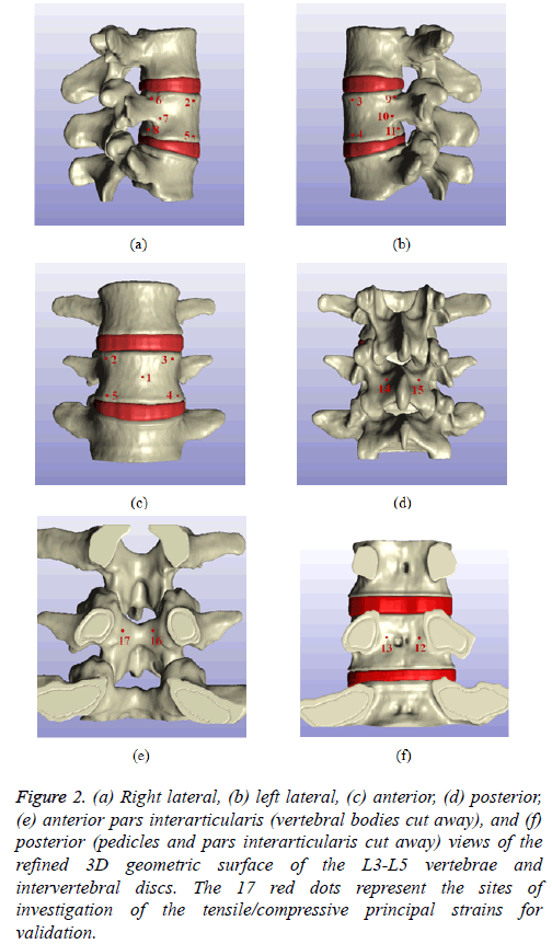
The geometric shape of the vertebral surface can be changed dramatically according to the image processing technique. Therefore, a proper processing tool should be implemented. For example, the cancellous bone within the vertebral cortical bone can be represented by either the ‘morphological close’ or ‘cavity fill’ option. Furthermore, the initial spinal surface is quite rough. Hence, an additional image processing procedure should be introduced. In this study, the ‘recursive Gaussian smoothing’ function was adopted for the surface treatment of the lumbar spine. Based on the aforementioned ScanIP functions, the refined 3D geometric surface of the L3-L5 was generated (Figure 2). As shown in this figure, the anatomical structures of the extremely complex lumbar spine, including the superior/inferior vertebral notches, articular processes, articular facets, spinous process, and intervertebral discs, can be identified.
Figure 2: (a) Right lateral, (b) left lateral, (c) anterior, (d) posterior, (e) anterior pars interarticularis (vertebral bodies cut away), and (f) posterior (pedicles and pars interarticularis cut away) views of the refined 3D geometric surface of the L3-L5 vertebrae and intervertebral discs. The 17 red dots represent the sites of investigation of the tensile/compressive principal strains for validation.
In the human spine, each vertebral body is connected between the superior and the inferior articular facets, as well as between the intervertebral discs and the vertebral bodies. Accordingly, the spinal internal stress induced by the uniaxial force, torsion, and bending, can be remarkably reduced, and critical damage/ fracture will not occur. Hence, in order to describe the actual spinal behavior under arbitrary loads and moments, the aforementioned inosculation was taken into account in the 3D geometric surface.
FE models and contact conditions
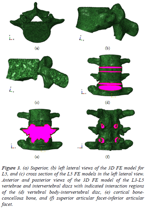
The mesh for the L5 vertebra was constructed using the ScanIP +FE Module (Figures 3a and 3b). The element type was a tennode quadratic tetrahedral element (C3D10 in ABAQUS), and the total number of elements was approximately 57,000. In the L5 FE model, two types of bone states, namely, the fully-filled with cortical bone (Type 1), and the cortical bone with a cancellous bone core (Type 2), were deliberated to identify the effects of the existence of the central core of bone. As shown in a cross section of L5, the inner domain of the single vertebra is covered by tetrahedral elements (Figure 3c). However, material properties for the cortical bone only, and the cortical bone and cancellous bone core were adopted prior to FEA.
Figure 3: (a) Superior, (b) left lateral views of the 3D FE model for L5, and (c) cross section of the L5 FE models in the left lateral view. Anterior and posterior views of the 3D FE model of the L3-L5 vertebrae and intervertebral discs with indicated interaction regions of the (d) vertebral body-intervertebral disc, (e) cortical bonecancellous bone, and (f) superior articular facet-inferior articular facet.
On the other hand, the mesh for the L3-L5 vertebrae and the associated intervertebral discs was also constructed using the same software (Figure 3d). The element type was a four-node linear tetrahedral element, and the total number of elements was approximately 365,000. In the L3-L5 FE model, there are three types of significant interfaces, the vertebral bodyintervertebral disc, the cortical bone-cancellous bone, and the superior articular facet-inferior articular facet. Hence, a proper contact condition between these interfaces was implemented prior to FEA in the present study (Figures 3d-3f).
One of the crucial factors to be postulated during FEA of the spine is the friction effect between different materials. In previous research studies related to the interfaces between the human bone and ligaments, and bone and instrumentation [12-15], different friction coefficient values were used for the human joints. However, these factors, especially the friction coefficient of the superior-inferior articular facets and the friction of the intervertebral disc-vertebral body, vary widely according to the conditions of the experimental facilities, test specimens, and experimenter. Therefore, in the present study, a 0.1 friction coefficient value was postulated for each interface since this coefficient was typically selected among prior researchers [14,15]. The contact problems of articular facets and intervertebral disc joints were calculated nonlinearly using surface-to-surface contact elements at a distance of approximately 0.5 mm.
Loading, boundary conditions, and material properties
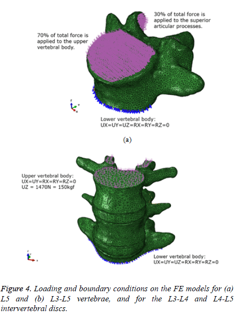
The loading and boundary conditions for a series of FEA under compressive loads are shown in Figure 4. In the case of L5, the lower vertebral body was totally fixed, and the upper vertebral body and two sets of superior articular processes received approximately 450 N, which is equivalent to the body weight of a 70 kg person, including the trunk, head, and arms (Figure 4a). In particular, 70% and 30% of the total load were separately applied to the upper vertebral body and superior articular processes, respectively, as the facet joints can commonly carry 10% to 40% of the compressive loads of the total forces subjected to the vertebrae [6].
On the other hand, in the case of the L3-L5 vertebrae, the lower vertebral body of L5 was totally fixed, and a load of almost 1470 N, which is equal to a body weight of a 150 kg person, was applied to the upper vertebral body of L3 (Figure 4b). This loading condition is equivalent to the applied load value of the uniaxial compressive test for the cadaveric lumbar spine L4 and the L4-L5 intervertebral discs [16]. However, the effects of ligaments, such as the anterior and posterior longitudinal ligaments, supraspinous and interspinous ligaments, and the intertransverse ligament, were not considered since the numerical analysis results were compared with those from in vitro static compression experiments on a cadaveric lumbar spine.
The structural members of the single and segmental spines were considered as linear elastic isotropic materials. In particular, as mentioned earlier, two types of bones, cancellous and cortical, were adopted during FEA. The intervertebral disc comprises the nucleus pulposus and annulus fibrosus [17,18] but in the present study the disc was postulated as a homogeneous material, and a certain intermediate value for the material properties of the nucleus pulposus and the annulus fibrosus was determined.
The elastic moduli for cancellous, cortical bones, and the intervertebral disc, were 100 MPa, 12,000 MPa and 100 MPa, respectively, and the Poisson ratio values for above materials were 0.3, 0.3, and 0.4, respectively [18,19].
Results
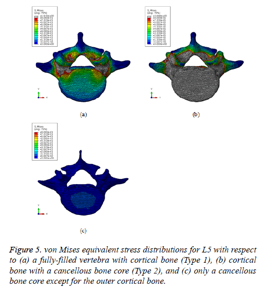
Based on the proposed FEA technique, the von Mises equivalent stress distributions were estimated for L5 with respect to types 1 and 2 vertebrae (Figure 5). In the case of Type 1, the maximum equivalent stresses were found to be positioned around the vertebral arch and pedicle (or superior vertebral notch) (Figure 5a). In particular, the stress concentration amounts in the pedicle domain ranged from 0.8 MPa to 1.91 MPa, indicated in gray.
In the case of type 2, it is confirmed that the maximum equivalent stresses were still observed near the superior vertebral notch, but high stress values were also found on the upper vertebral body (Figure 5b). Furthermore, the most significant difference in the type 2 case, regarding the elicited stress response, was the fact that the maximum equivalent stress was considerably increased from 1.91 MPa to 2.62 MPa. However, the critical stress increase could not be observed in the cancellous bone core, for which the maximum equivalent stress was 0.067 MPa (Figure 5c).
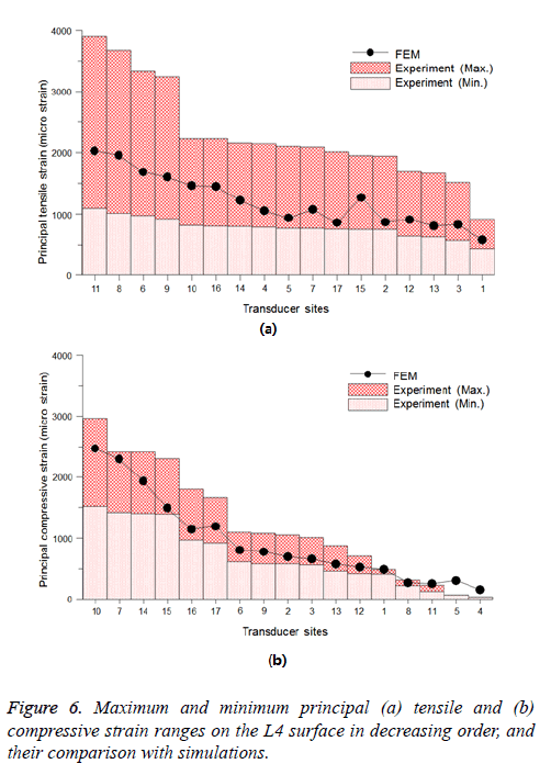
On the other hand, the principal strains on 17 positions of the lumbar spine at L4 were identified (Figure 2) to investigate the structural behaviors of the L3-L5 vertebrae under compressive loads. As a result of the FEA, the principal tensile and compressive strains at all transducer sites with loads of 1,470 N were investigated (Figure 6). In these charts, the experimentally measured maximum and minimum strains are listed in a decreasing order of strain magnitude. The bar chart represents the minimum to maximum principal strain data [16], and the black solid line represents the present FEA results. As shown in this chart, the highest and the lowest tensile principal strains were generated on the upper (site numbers 6 and 9) and on the lower (site numbers 8 and 11) posterior vertebral rims, and at the center of the anterior surface of the vertebral body (site number 1), respectively. Relatively low tensile strain values were elicited on the upper anterior vertebral body (site numbers 2 and 3), and the posterior vertebral body (site numbers 12 and 13).
On the other hand, the highest and the lowest compressive principal strains were recorded near the bases of the pedicles (site numbers 7 and 10) and on the superficial and deep surfaces of the pars interarticularis (site numbers 14 and 15), and the lower anterior (site numbers 4 and 5) and lower posterior (site numbers 8 and 11) vertebral rims.
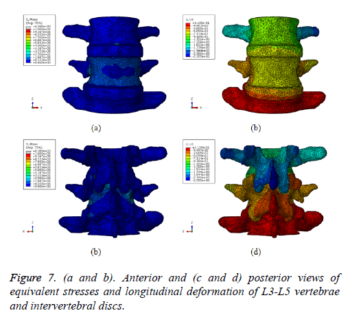
The contour for the equivalent stresses and longitudinal deformation (Z-direction displacement) of the L3-L5 vertebrae and intervertebral discs was also calculated (Figure 7). The stress concentrations occurred on the vertebral arch and pedicle of the L4 vertebra at magnitudes ranging from 8 MPa to 25 MPa. In particular, 35 MPa to 75 MPa of equivalent stresses were generated on the pedicle of L4. Similar to the L5 type 2 simulation results, larger stresses occurred in cortical bone, while there was no significant stress increase at the cancellous bone core or at the intervertebral discs. The maximum longitudinal deformation was measured to be -2.355 mm at the upper vertebral body of L3.
Discussion
In this study, the computational technique for an accurate FE model construction, including CT image control using ScanIP, preparation of the 3D geometric surface and tetrahedral mesh, and implementation of the cortical bone with the cancellous bone core and the interface between heterogeneous materials, is presented. Based on the developed FE model, the mechanical behaviors of lumbar spine under static compressive loads, namely, the position and amount of von Mises equivalent stresses and principal strains were quantitatively predicted.
Based on the numerical analysis results of L5, high levels of equivalent stresses were generated around the pedicle in the fully filled cortical bone case, and in the vertebral arch and body in the case of cortical bone with a cancellous bone core, respectively. Although only 30% of the total force, namely, only 135 N was applied to both superior articular processes, the critical stress value that can lead to structural failure was listed in these domains. This is because the shape of the pedicle is similar to the blunt notch, and accordingly, the internal material stress in this region can be noticeably increased. Therefore, it is concluded that the vertebral arch, among other vertebral spine regions, can be readily damaged by a small amount of static/dynamic load [20].
On the other hand, the maximum equivalent stress in the case of cortical bone with a cancellous bone core was increased by approximately 37% (from 1.91 MPa to 2.62 MPa) in comparison to the fully filled cortical bone case. In particular, most of the elicited stresses with large values were identified on the outer cortical bone, while the noticeable rise of stresses was not shown to exist on the inner part of cancellous bone. In contrast, the large growth of vertical (Z-direction) displacement was manifested on the cancellous bone core rather than on the cortical bone. The reason was that the cancellous bone cannot resist the external load since the elastic stiffness is not as high as that of cortical bone. Accordingly, it can be confirmed that the outer, hard cortical bone, resists the external energy induced by compressive loads, while the inner soft cancellous bone absorbs the external energy [21,22]. Hence, the spinal fracture can take place on the cortical bone region, such as the surface of the vertebral arch, as well as the surface of the vertebral body, under arbitrary monotonic and dynamic loads.
Another important factor is that the absorption of external energy was not estimated in the fully filled cortical bone case owing to the absence of a cancellous bone core. The FEA results of this case represent the unrealistic and meaningless mechanical behavior of human spine, and for this reason, the heterogeneous bone state should be allowed for describing the real spine behavior during simulation.
The comparison of the maximum equivalent stress between a previously published study [6] and this simulation was also carried out (Table 1). As shown in this table and Figure 5, it is confirmed that the magnitude as well as the contour of the maximum stress matched well with that reported in the literature.
| Type | Prior published study [6] | Present study | Error (%) |
|---|---|---|---|
| Type 1 | 1.92 MPa | 1.91 MPa | 0.52 |
| Type 2 | 2.59 MPa | 2.62 MPa | 1.16 |
| Average error (%) | 0.84 |
Table 1. Comparison of the maximum equivalent stress between the literature and simulation.
In the numerical analysis results of L3-L5, the highest tensile and compressive principal strains occurred near the upper and lower posterior vertebral rims and the bases of the pedicles and on the superficial and deep surfaces of the pars interarticularis of L4, respectively, under compressive loads. In particular, the absolute value of the principal strain in the upper and lower posterior vertebral rims, and the roots of the pedicle (that ranged from 3,400 to 4,000 micro strain units) is much higher than its value in the other vertebral regions (Figure 6). In addition, critical equivalent stresses that ranged from 35 MPa to 75 MPa, existed on the pedicle of the L4 (Figure 7). Moreover, the fracture stress of lumbar vertebrae measured by compressive tests of a cadaver spine approximately ranged from 7 MPa to 14 MPa [23,24]. Through the stress and strain behaviors, it can be concluded that the critical vertebral damage can be initiated in these domains, and it can lead to the catastrophic fracture of lumbar vertebral structures. Hence, the quantitative evaluation and prediction of damage growth and lifetime under arbitrary loads might be feasible if the advanced damage model for human bone will be implemented into the present stress and strain analysis method.
The comparison of the tensile and compressive principal strains between the cadaver experiments [16] and the FEA was also conducted (Figure 6). Although the comparison of the equivalent stress between the literature and the simulation was not possible owing to the limitation of the experimental results, the numerically predicted principal strains at most of the transducer sites matched well the reported data.
On the other hand, there was a limitation and a simplification during the simulation. In fact, there are some deviations of Young’s modulus and Poison ratio values with respect to age and gender. Moreover, in order to statistically describe the material properties for the structural members of the spine, empirical and analytical models were previously proposed by other researchers [25]. However, in the present study, the material properties of cortical and cancellous bones, and intervertebral discs, were postulated as isotropic and homogeneous to simplify the FE procedure. Despite this limitation, the proposed FE modeling and analysis procedure might be useful for identifying the magnitude and distribution of stress/strain for the human spine structure.
Based on the aforementioned comparative study of L5 and L3- L5, the damage initiation and growth characteristics of lumbar spine under impact loads, with respect to bone density, intact and osteoporotic states, will be computationally predicted using the proposed simulation procedure and damage-coupled constitutive model in a future study.
Acknowledgements
This research was supported by Basic Science Research Program through the National Research Foundation of Korea (NRF) funded by the Ministry of Education (NRF-2016R1D1A1B03934304). This research was also supported by the Bio and Medical Technology Development Program of the NRF funded by the Korean government, MSIP (NRF-2016M3A9E8942063).
References
- Rohlmann A, Bauer L, Zander T, Bergmann G, Wilke HJ. Determination of trunk muscle forces for flexion and extension by using a validated finite element model of the lumbar spine and measured in vivo data. J Biomech 2006; 39: 981-989.
- Shirazi-Adl A. Analysis of large compression loads on lumbar spine in flexion and in torsion using a novel wrapping element. J Biomech 2006; 39: 267-275.
- Noailly J, Wilke HJ, Planell JA, Lacroix D. How does the geometry affect the internal biomechanics of a lumbar spine bi-segment finite element model? Consequences on the validation process. J Biomech 2007; 40: 2414-2425.
- Niemeyer F, Wilke HJ, Schmidt H. Geometry strongly influences the response of numerical models of the lumbar spine-A probabilistic finite element analysis. J Biomech 2012; 45: 1414-1423.
- Schmidt H, Bashkuev M, Dreischarf M, Rohlmann A, Duda G, Wilke HJ, Shirazi-Adl A, Computational biomechanics of a lumbar motion segment in pure and combined shear loads. J Biomech 2013; 46: 2513-2521.
- Nabhani F, Wake M. Computer modelling and stress analysis of the lumbar spine. J Mater Proc Technol 2002; 127: 40-47.
- Qiu TX, Teo EC, Yan YB, Lei W. Finite element modeling of a 3D coupled foot-boot model. Med Eng Phys 2011; 33: 1228-1233.
- Assaad W, Misra S. Combining ultrasound-based elasticity estimation and FE models to predict 3D target displacement. Med Eng Phys 2013; 35: 549-554.
- Avery CME, Bujtar P, Simonovics J, Dezsi T, Varadi K, Sandor GKB, Pan J. A finite element analysis of bone plates available for prophylactic internal fixation of the radial osteocutaneous donor site using the sheep tibia model. Med Eng Phys 2013; 35: 1421-1430.
- Rao C, Fitzpatrick CK, Rullkoetter PJ, Maletsky LP, Kim RH, Laz PJ. A statistical finite element model of the knee accounting for shape and alignment variability. Med Eng Phys 2013; 35: 1450-1456.
- Alimohammadi M, Agu O, Balabani S, Díaz-Zuccarini V. Development of a patient-specific simulation tool to analyse aortic dissections: Assessment of mixed patient-specific flow and pressure boundary conditions. Med Eng Phys 2014; 36: 275-284.
- Merkher Y, Sivan S, Etsion I, Maroudas A, Halperin G, Yosef A. A rational human joint friction test using a human cartilage-on-cartilage arrangement. Tribol Lett 2006; 22: 29-36.
- Fantigrossi A, Galbusera F, Raimondi MT, Sassi M, Fornari M. Biomechanical analysis of cages for posterior lumbar interbody fusion. Med Eng Phys 2007; 29: 101-109.
- Galbusera F, Bellini CM, Raimondi MT, Fornari M, Assietti R. Cervical spine biomechanics following implantation of a disc prosthesis. Med Eng Phys 2008; 30: 1127-1133.
- Tsuang YH, Chiang YF, Hung CY, Wei HW, Huang CH, Cheng CK. Comparison of cage application modality in posterior lumbar interbody fusion with posterior instrumentation-A finite element study. Med Eng Phys 2009; 31: 565-570.
- Shah JS, Hampson WG, Jayson MI. The distribution of surface strain in the cadaveric lumbar spine. J Bone Joint Surg Br 1978; 60-60B: 246-251.
- Schuenke M, Schulte E, Schumacher U. Thieme Atlas of anatomy: general anatomy and musculoskeletal system. Thieme 2010.
- Kurutz M, Oroszvary L. Finite element analysis of weight bath hydrotraction treatment of degenerated lumbar spine segments in elastic phase. J Biomech 2010; 43: 433-441.
- Lavaste F, Skalli W, Robin S, Roy-Camille R, Mazel C. Three-dimensional geometrical and mechanical modelling of lumbar spine. J Biomech 1992; 25: 1153-1164.
- Hall SJ. Basic biomechanics. McGraw-Hill 1999.
- Gibson LJ. The mechanical behaviour of cancellous bone. J Biomech 1985; 18: 317-328.
- Mosekilde L, Mosekilde L, Danielsen CC. Biomechanical competence of vertebral trabecular bone in relation to ash density and age in normal individuals. Bone 1987; 8: 79-85.
- Rockoff SD, Sweet E, Bleustein J. The relative contribution of trabecular and cortical bone to the strength of human lumbar vertebrae. Calcified Tissue Res 1969; 3: 163-175.
- Currey JD. The mechanical properties of bone. Clin Orthop Relat Res 1970; 73: 209-231.
- Nicholson PHF, Cheng XG, Lowet G, Boonen S, Davie MWJ, Dequeker J, Van der Perre G. Structural and material mechanical properties of human vertebral cancellous bone. Med Eng Phys 1997; 19: 729-737.

