Research Article - Biomedical Research (2017) Artificial Intelligent Techniques for Bio Medical Signal Processing: Edition-I
High performance VLSI architecture to improve contrast in digital mammographies using discrete wavelet transform
V Geetha* and G MurugesanDepartment of Electronics and Communication Engineering, Kongu Engineering College, Perundurai, Erode, India
- *Corresponding Author:
- V Geetha
Department of Electronics and Communication Engineering
Kongu Engineering College India
Accepted date: January 17, 2017
Abstract
This work proposed a signal processing method known as the parallel lifting-based Canonical Signed Digit (CSD) 2D Discrete Wavelet Transform (DWT) infrastructure to realize a multiplierless architecture with lesser hardware complexity, smaller area and power consumption. The flipping structure of the lifting scheme can be recognized to reduce the longest critical path. CSD based structure is demonstrated with only adders and free of multipliers. A stripe based scanning method is adopted in order to achieve an efficient memory. JPEG 2000 lossy 9/7 filter is structured and the same scanning method with CSD is used to design 6/10 filter to contribute the evidence for the proposed methodology. In the existing method, memory efficiency is achieved with less speed. The new architecture is proposed using CSD multiplier with more speed. The filter coefficients are multiplied by 256 and are converted to integer form and then CSD representation is considered. The suggested architecture provides multiplierless infrastructure for DWT utilizing CSD. This infrastructure is appropriate for high speed online applications with less area and power consumption. For an N× (N+1) image, the suggested CSD based lifting infrastructure utilizes solely 3N temporal memory, 2S transposition memory as well as Tm+Ta critical path. The proposed technique can be effectively adapted for improving contrast in mammograms which is crucial in Telemedicine applications where bandwidth and hardware constraints exist. Simulation results show the effectiveness of the proposed technique.
Keywords
Ground penetrating radar (GPR), Discrete wavelet transform (DWT), Canonical signed digit (CSD), Adapted local cosine transform (CPD), 9/7 filter, 6/10 filter, Minimum distance/percentage principle (MDPP)
Introduction
Mammograms may be utilized for detecting characteristic masses or microcalcifications. For taking mammograms, radiologists assist the patients in positioning their breast between two small plates where X-rays pass through the breast tissue. The plates then compress the breast for an instant for taking the X-ray image. Both breasts are compressed to a thickness of around 6 cm and X-ray images are taken perpendicular to the plane of compression [1]. The various densities of breast tissue attenuate the X-ray distinctly and translates into varying degrees of brightness on the resultant image.
The DWT localizes signals in the time as well as frequency domains. DWT has a huge part to play in image processing applications. The standard image coding JPEG 2000 has adopted DWT as its transform coder due to its advantages over other transforms. Hardware implementation of DWT is possible in two ways mainly convolution based technique and lifting based technique. Traditional execution of DWT is through convolution or FIR filter bank structure. Such execution requires huge arithmetic calculations as well as storage. Therefore it is not favorable for high speed or low power image processing applications. A newly developed formula, which is suitable to achieve high speed as well as low power, called lifting based wavelet transform has been proposed. Here, the high pass coefficients as well as low pass coefficients may be decomposed into order of upper triangular matrix and lower triangular matrix. This method offers great speed with no auxiliary memory and less arithmetic operations. The bottleneck with lifting based architectures is its long CPD. Much architecture has been proposed on shortening the crucial path delay [2-5]. The CPDs in these architectures varies from Tm+5Ta to Tm at the expense of memory size and arithmetic resources, few architectures are proposed to achieve memory efficiency, which is composed of temporal and transposition memory [6].
Line based scanning technique is suggested in [6] and parallel scanning technique is suggested in [4] to achieve memory efficiency. Block based scanning technique is suggested in [7] from which a better tradeoff between the size of internal memory as well as how many times the external memory access is accomplished. Parallel stripe based data scanning technique permits a trade of between external memory bandwidth as well as internal buffer size is established in [8]. Wavelets are an integral component of modern computations. They are widely utilized in every domain in image processing, medical data analyses and so on that focus on throwing light on wavelets via an investigation into the diverse literature on VLSI structures and their possible applications including Mammography [9,10]. Iqbal et al. [11] showed the improvements in contrast of medical images using DWT.
Ezhilarasi and Nirmalkumar alleviated the image degradation at higher Compression Ratios (CR) and suggested an integrated compression method that fuses Quadrant Tree Decomposition (QTD) as well as lifting based DWT for providing encouraging results with higher compression at lower bit rates with no loss of image data [12]. Generally, noise is present in digital images because of the imaging devices as well as quantizations. Because of non-linear processing, noise might be amplified which will decrease the utility of contrast enhancement, which is employed on features of particular interest in mammographies, which include masses, spicules or even microcalcifications. The method led to superior results than those got through usage of state of the art protocols which included unsharp masking as well as adaptive histogram equalization [13].
In this paper, a short CPD of Tm+Ta is achieved with the most memory effective design. Amongst the parallel based architecture [8] is the most memory efficient with the same quantity of multipliers as well as adders along with same computation time. Because of parallel architecture the hardware complexity is more with 10S number of multipliers where S represents the stripe width. In this summary a novel CSD based architecture from which the hardware complexity is reduced is introduced. CSD is popular representation of number with minimum number of nonzero digits and it has unique nature [14,15]. The filter coefficients are considered in the form of floating point numbers and hence the number of bits for representation is varying. Here the coefficients are converted to integers by multiplying with 256. Then the CSD representation is taken for these integers. The rest of the papers are structured into the existing methods followed by the proposed method. The final section comprises the implementation results of the proposed architecture followed a brief conclusion.
Existing Method
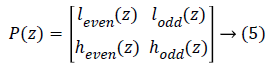
Lifting scheme and flipping structure: The Euclidean algorithm is used in lifting scheme, by which the polyphase matrix is factorized into alternative upper triangular matrix, lower triangular matrix as well as a diagonal matrix [16]. The polyphase matrix P (z) of a wavelet transform is given below in equation (5):
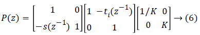
The above polyphase matrix can be factorized into equation (6):
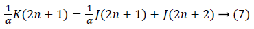
Flipping structure is used to reduce CPD. Flipping can be achieved by taking inverse of the multiplier coefficient with every edge on the feed forward cut set via the chosen multiplier. Hence no additional multipliers are required. This is shown in equation (7) and (8),

Stripe based scanning technique: Overlapped stripe based scanning technique is used to achieve less memory and computation time. Let the image size is considered as N x (N +1) with the 1st column of zero padded. For S parallel Processing Units (PU) a stripe width of 2S+1, with 1 column overlapped between 2 neighbour stripes is used. Row DWT starts its computation before column DWT. Every pixel from A (0, 0) to A (0, 2S) of the 1st row are fed concurrently in the first cycle and this scanning continues until it reaches A (N, 0) to A (N, 2S). As soon as the pixels are fed the row DWT starts its computation and for each clock cycle it produces one pair of intermediate High Pass (HP) as well as Low Pass (LP) which is passed to the Transposition Register (TP) before given to the column DWT. The major advantage of this scanning method is once the output of row DWT is computed it allows the column DWT to start its computation, which results in constant latency and it is not dependent on both N and S.
DWT architecture: Implementation of the data flow through Data Processing Pipe (DPP) depends upon the number of stripes. As S=4, four DPPs each with four Computational Units (CU) is needed for row DWT. Each CU process with constant inverse coefficients of α, β, γ, and δ. Each CU receives three inputs I0, I1 and I3 and generates two partial results. The row processing unit is constructed with S DPPs with stripe width of 2S+1which accepts 2S+1 pixel every clock cycle. In this the partial result from sth DPP is given as input to the (s+1)th DPP, where s=S-1. The intermediate outputs of the row DWT are fed into the transposition register. For every clock cycle, each pipe in the Row DWT generates two outputs, HP and LP. These are fed to TR, which stores the intermediate results and transposes these values and passes two H or L in alternate clock cycles to the column DWT. The intermediate outputs from TR are given as inputs to the column DWT.As the partial results have to be processed after two clock cycles; they need shift registers of length two. The four outputs from the column DWT are (LL, LH) (HL, HH). In this structure column DWT starts its computation immediately the intermediate results from Row DWT.
Proposed Method
CSD number system is one which is used for the purpose of converting a floating-point value in a two's complement demonstration. The architecture with 9/7 filter is given for a dedicated DWT core for JPEG2000. For the purpose of comparison, 6/10 filter is also considered with the same CSD architecture. Accordingly the filter coefficients are fixed. Hence multiplications may be optimized even more. The finiteprecision coefficients are desired to be within justifiable error range. Also the filter coefficients in their CSD form representation decrease the count of non-zero digits and the count of adders.
Lifting coefficients: The magnitude of the lifting coefficients for 9/7 filter range from 0.046875 to 1.58613. For the conversion to integers, the coefficients are left shifted by 8 bits instead of multiplied by 256. The new range of lifting coefficients after shifting is from 12 to 406, which demand 10 bits (2’s complement representation) for the representation. At the end of the process the product is right shifted by 8 to obtain the essential outcome for every multiplication. Rounding is done for the 8 least significant bits during hardware implementation.
Canonical signed digit: For the purpose of reduction in the number of addition operations used during multiplication, CSD format is used. CSD format possesses a ternary set as conflicting to a binary set in its illustration .The symbols utilized in the CSD format are represented as {-1, 0, 1}. This conversion from binary to CSD is done by grouping the 1s consecutively present in the binary representation and changes them to a ternary representation. Processing starts from the rightmost one and proceeding left till the last one. Through this, CSD abstraction has no two adjacent non-zero digits. It is substantiated that the number of operations never exceeds n/2 and on an average it can be decreased to n/3.Filter coefficientsα, β, γ and δ represented in CSD form for 9/7 filter are, α=-1.58613432, β=-0.052980118, γ=0.88291 1076 as well as δ=0.443506852.
In CSD based multiplication the filter coefficient is considered as multiplier and input as a multiplicand. Initially equivalent binary values for both have to be taken. Based on the position of one in filter coefficient, right shift operation for input have to be performed. Once the shifting operation is completed, the values have to be appended for obtaining the output. Suppose if the filter coefficient is negative then two’s complement have to be taken for the output produced.
Structure of 9/7 filter: The MDPP with CSD consist of four cells namely α, β, γ, δ and their coefficients. It possesses 3 inputs which are X0, X1 as well as X2 along with 3 partial inputs PRI1, PRI2and PRI3. Their corresponding partial outputs PRO1, PRO2 and PRO3 and a low-pass L and high-pass H outputs are produced through the schedule of precise pixel input, partial outcomes as well as intermediary outcomes of MDPP.
The Row Processing Unit (RPU) consists of four MDPPs and three shift registers of length N. Shift registers are utilized for storing the partial outputs created by last MDPP and is propagated as partial input to first MDPP. The intermediary outcome is generated by the RPU are fed into TR. A high pass filter output along with a low pass filter output from RPU is passed to the TR present such that the output generated is alternately high as well as low. Output from the transposition register is given to Column Processing Unit (CPU). Once the input is received, the corresponding high pass as well as low pass outputs are computed which is to be scaled with the scaling coefficient in order to normalize the output value subsequently that the thorough reconstruction of image is formed. The data flow graph of flipping strategy is obtained from the equations given below in equation (9 to 12)


Structure of 6/10 filter: The MDPP consist of seven cells A, B, C, D, E, F, G as well as their coefficients. It possesses 3 inputs which are X0, X1 as well as X2 along with six partial inputs PRI1, PRI2, PRI3, PRI4, PRI5 and PRI6. Their corresponding partial outputs PRO1, PRO2, PRO3, PRO4, PRO5 and PRO6 and a pair of low as well as high-pass output L as well as H are generated through the schedule of correct pixel input, partial outcomes as well as intermediary outcomes of MDPP.
The data flow graph of flipping strategy is obtained from the equations given below in equation (13 to 19):


Performance Comparison
Hardware estimation: Table 1 shows the assessment between the existing and the proposed design of architecture with regard to the quantity of multipliers, adders, registers, transposition buffers, temporal buffers and critical path. Compared with one of the best design in [17], the registers used in existing architecture are reduced from 28S to 22S as well as the delay in the critical route is found to be reduced from Tm+2Ta to 2Ta.
| Existing work | Multiplier | Adder | Register | Transposition buffer | Temporal buffer | Critical path |
|---|---|---|---|---|---|---|
| Tian et al. [7] | 10S | 16S | 28S | NS+N | 3N | Tm+2Ta |
| Mohanty et al. [18] | 9S | 16S | 20S | 3N | 3N | Tm+2Ta |
| Mohanty et al. [18] | 9S | 16S | 15S | N | 3N | Tm+2Ta |
| Ching and Yusong [8] | 10S | 16S | 22S | 2S | 3N | Tm+Ta |
| Proposed work | 0 | 24S | 22S | 2S | 3N | 2Ta |
Table 1. Comparison between Proposed CSD Based Architecture and Various Current Infrastructures in Hardware Resources (For 9/7 Filter Lifting Scheme Based DWT).
In the best existing design in [7], there are 10S multipliers present, means that for S=4, 40 multipliers are present. In contrast to current work the suggested work is multiplier less architecture with the increased adders and the critical path delay, registers, temporal buffer and transposition register is found to be same. The Transposition buffer is reduced from NS +N in [17] to 2S in our proposed method. As a result the area utilized and power consumption is reduced.
Implementation: Current best parallel 2D DWT infrastructure was modelled as well as validated and the proposed CSD design for 9/7 and 6/10 filter with S=4 in structural VHDL language. The design was synthesized in the Virtex 5, xc5vlx110 device in Xilinx ISE 12.3. The synthesized results are tabulated in Tables 2 and 3 for 9/7 filter, where the reduction in (%) over the best existing method [8] and the proposed method are indicated.
| Parameter | Existing method | Proposed method | Reduction in (%) |
|---|---|---|---|
| Delay | 17.340 ns | 6.921ns | 60.09 |
| Power consumption | 1184.0 m W | 1163.04mW | 1.77 |
| Memory used | 1022504 kb | 413928 kb | 59.52 |
| 32 bit Adders | 1 | 1 | - |
| Xors | 22008 | 1792 | 91.86 |
| Slice logic utilization: | |||
| Number of slice LUTs | 13146 | 7524 | 42.77 |
| Number used as logic | 12602 | 6980 | 44.61 |
| Number used as memory | 544 | 544 | - |
Table 2. Comparison between Suggested CSD Based Infrastructure and Various Current Infrastructures in Terms of Different Parameters (For 9/7 Filter Lifting Scheme Based DWT).
| Slice logic distribution: | |||
|---|---|---|---|
| Number of LUT-FF pair used | 13922 | 8156 | 41.42 |
| Number with an unused FF | 11477 | 5703 | 50.31 |
| Number with an unused LUT | 776 | 632 | 18.56 |
| Number of IOs | 146 | 146 | - |
Table 3. Comparison between Suggested CSD Based Infrastructure and Various Current Infrastructures in Terms of Different Parameters (For 9/7 Filter Lifting Scheme Based DWT).
The results show the reduction in delay as 61.7%, power consumption as 0.188%. Memory usage in the existing architecture is 481196 kb whereas in the proposed system it is 364648 kb. Hence reduction in memory usage is 24.22% and XORs are reduced from 16416 in the existing structure to 1024 in the proposed scheme shows reduction as 93.76%. From the results shown in Table 4 the proposed structure for 6/10 filter is multiplier less with the same registers, memory and critical path. Instead of 16S multipliers, the proposed system is multiplier less at the expense of increase of adders from 28S to 42S. The proposed structure has 6.921ns delay whereas the existing structure has 17.340 ns. Hence a reduction of 60.09% in delay is achieved. The number of 32 bit adders is one, in both the proposed and the existing system. The power consumption drops from 1184.03 mW to 1163.04 mW shows a reduction of 1.77%. Memory usage in the existing scheme is 1022504 kilobytes which is 59.52% less when compared with 413928 kilobytes in the proposed system as shown in Table 5. Figure 1 shows the sample image processed.
| Architecture | Multiplier | Adder | Register | Transposition buffer | Temporal buffer | Critical path |
|---|---|---|---|---|---|---|
| Existing work [7] | 16S | 28S | 22S | 2S | 3N | Tm+Ta |
| Proposed work | 0 | 42S | 22S | 2S | 3N | 2Ta |
Table 4. Comparison between Suggested and Current Infrastructures in Hardware Resources (For 6/10 Lifting Based DWT).
| Parameter | Existing method | Proposed method | Reduction in (%) |
|---|---|---|---|
| Delay | 13.850 ns | 5.305 ns | 61.7 |
| Power consumption | 1153.61 Mw | 1151.43 mW | 0.188 |
| Memory used | 481196 kb | 364648 kb | 24.22 |
| 32 bit Adders | 33 | 1* | 96.96 |
| Xors | 16416 | 1024 | 93.76 |
| Slice logic utilization: | |||
| Number of slice LUTs | 5981 | 3581 | 40.12 |
| Number used as logic | 5677 | 3277 | 42.27 |
| Number used as memory | 304 | 304 | - |
| Slice logic distribution: | |||
| Number of LUT-FF pair used | 6411 | 3968 | 38.1 |
| Number with an unused FF | 4974 | 2519 | 49.35 |
| Number with an unused LUT | 430 | 387 | 10 |
| Number of IOs | 146 | 146 | -- |
Table 5. Comparison between Suggested and Current Infrastructures in Hardware Resources (For 6/10 Lifting Based DWT).

Figure 1: The left image is the original image and the image on the right is the contrast enhanced image.
Conclusion
According to Ching and Yusong Hu [8] a total of 40 multipliers for S=4 is needed for 9/7 filter which occupies a widespread area and additional power consumption. In multipliers power consumption is governed by its number of non-zero digits. Hence in the proposed system CSD based methodology is adopted. A comprehensive analysis is accomplished and the design was synthesized in the Virtex 5, xc5vlx110 device in Xilinx ISE 12.3 to compare the proposed architecture of 9/7 filter with other by now prevalent architectures. Comparison is done with regard to hardware anonymity in the suggested design, crucial path delay of the suggested design, storage size used in the system, computation time of the system and throughput of the design. For endorsing the proposed design, we modeled the 6/10 filter based on the modified flipping architecture based on the lifting scheme using the same stripe based scanning method. We modeled, synthesized in the same platform and compared this architecture with the proposed CSD based structure. The proposed structure shows increased speed, reduced power consumption with reduced storage area. Compared to the best existing lifting based 2D DWT structure, the newly designed CSD based structure involves fairly fewer arithmetic resources as well as presents a high throughput rate with the same quantity of registers and the same critical route.
References
- Habibi Aghdam H, Puig D, Solanas A. A Probabilistic Approach for Breast Boundary Extraction in Mammograms. Comput Math Methods Med 2013.
- Shi G, Liu W, Zhang L, Li F. An efficient folded architecture for lifting-based discrete wavelet transform. IEEE Transact Circuits Syst II: Express Briefs 2009; 56: 290-294.
- Wu BF, Lin CF. A high-performance and memory-efficient pipeline architecture for the 5/3 and 9/7 discrete wavelet transform of JPEG2000 codec. IEEE Transact Circuits Syst Video Technol 2005; 15: 1615-1628.
- Zhang W, Jiang Z, Gao Z, Liu Y. An efficient VLSI architecture for lifting-based discrete wavelet transform. IEEE Transact Circuits Syst II: Express Briefs 2012; 59: 158-162.
- Mohanty BK, Meher PK. Memory efficient modular VLSI architecture for highthroughput and low-latency implementation of multilevel lifting 2-D DWT. IEEE Transact Signal Process 2011; 59: 2072-2084.
- Huang CT, Tseng PC, Chen LG. Generic RAM-based architectures for two-dimensional discrete wavelet transform with line-based method. IEEE Transact Circuits Syst Video Technol 2005; 15: 910-920.
- Tian X, Wu L, Tan YH, Tian JW. Efficient multi-input/multi-output VLSI architecture for two-dimensional lifting-based discrete wavelet transform. IEEE Transact Comput 8: 1207-1211.
- Ching CJ, Yusong H. A memory efficient scalable architecture for 2D discrete wavelet transform. IEEE Trans Image Process 2011; 16: 607-614.
- Karobari FM, Bharathi SH. VLSI Architectures for 3D Discrete Wavelet Transform and Applications of Wavelet Transform–A Comprehensive Study. Int Res J Eng Technol 2015; 2: 46-52.
- Raghavendra U, Acharya UR, Fujita H, Gudigar A, Tan JH, Chokkadi S. Application of Gabor wavelet and Locality Sensitive Discriminant Analysis for automated identification of breast cancer using digitized mammogram images. Appl Soft Comput 2016; 46: 151-161.
- Iqbal MZ, Ghafoor A, Siddiqui AM, Riaz MM, Khalid U. Dual-tree complex wavelet transform and SVD based medical image resolution enhancement. Signal Processing 2014; 105: 430-437.
- Ezhilarasi P, Nirmalkumar P. Algorithmic Based VLSI Architecture of Integrated Image Compression for CMOS Image Sensor. Nat Acad Sci Lettr 2015; 38: 49-59.
- Laine A, Fan J, Yang W. Wavelets for contrast enhancement of digital mammography. IEEE Eng Med Biol Magazine 1995; 14: 536-550.
- Martínez-Peiró M, Boemo EI, Wanhammar L. Design of high-speed multiplierless filters using a nonrecursive signed common subexpression algorithm. IEEE Transact Circuits Syst II: Analog Digital Signal Process 2002; 49: 196-203.
- Ni SH, Huang YH, Lo KF, Lin DC. Buried pipe detection by ground penetrating radar using the discrete wavelet transform. Computers Geotechnics 2010, 37: 440-448.
- Daubechies I, Sweldens W. Factoring wavelet transforms into lifting steps. J Fourier Anal Appl 1998; 4: 247-269.
- Parhi KK. VLSI digital signal processing systems: design and implementation. John Wiley & Sons, 2007.
- Mohanty BK, Mahajan A, Meher PK. Area-and power-efficient architecture for high-throughput implementation of lifting 2-D DWT. IEEE Transact Circuits Syst II: Express Briefs 2014; 59: 434-438.