Short Communication - Biomedical Research (2018) Volume 29, Issue 8
A novel angular SiO2 electret-based electrostatic energy harvester for cardiac and neural implants
Suhaib Ahmed*, Vipan KakkarDepartment of Electronics and Communication Engineering, Shri Mata Vaishno Devi University, Katra, India
- *Corresponding Author:
- Suhaib Ahmed
Department of Electronics and Communication Engineering
Shri Mata Vaishno Devi University, India
Accepted date: September 18, 2017
DOI: 10.4066/biomedicalresearch.29-17-1324
Visit for more related articles at Biomedical ResearchAbstract
Energy harvesting as an alternate power source in miniaturized implantable medical devices, especially cardiac and neural implants has been investigated. An electret-based angular electrostatic energy harvester has been proposed along with a power management control circuit to harvest maximum possible energy. The proposed harvester incorporates the properties of both area-overlap and gap closing topologies to achieve larger capacitance variation with respect to displacement as is observed in the results. The maximum power that can be scavenged from the proposed harvester of size 2.5 × 3.5 mm2 at maximum displacement is 9.6 μW.
Keywords
Energy harvesting, Electrostatic conversion, Electret, Cardiac implant, Neural implant.
Introduction
Currently the problem of powering and replacing the batteries in miniaturized medical implantable devices especially cardiac and neural implants calls for the development of an alternate power source. The output mechanical energy of the heart is in the order of ~1 W out of which only 20~25% is consumed [1,2]. Therefore it might be possible to scavenge power from the micro-vibrations of the heart upto few μWs without affecting the natural functioning of the heart [3]. Based on the analysis and comparison of three different micro-vibration energy conversion techniques viz. electrostatic, electromagnetic and piezoelectric harvesters presented in [1,4-8], it is observed that the capacitive electrostatic micro-generators create high electric field energy density and consequently high power along with being easily realizable in Micro-Electro-Mechanical Systems (MEMS) and small in size. These electrostatic generators can be classified into electret based or electret-free based on the conversion principle [9]. The electret-free converters need an external power source to apply the charge cycle on the structure and hence cannot address the need of battery-less implants, whereas the electret based converters use electrets and thus have the ability to directly convert mechanical power into electrical. Some of the most wellknown and used electrets are presented in Table 1 [9]. For implants, size is a constraint, hence SiO2 based electret has been selected due to minimum thickness and high surface charge density and its bio-compatibility.
| Electret material | Relative permittivity | Maximum thickness | Dielectric strength (V/µm) | Surface charge density (mC/m2) |
|---|---|---|---|---|
| Teflon (PTFE/FEP/PFA) | 2.1 | ~100 µm | 100-140 | 0.1-0.25 |
| SiO2 | 4 | <3 µm | 500 | 05-11 |
| Parylene (C/HT) | 3 | ~10 µm | 270 | 0.5-1 |
| CYTOP | 2 | 20 µm | 110 | 01-2 |
| Teflon AF | 1.9 | 20 µm | 200 | 0.1-0.25 |
Table 1: Different available electrets and their properties.
Proposed Electrostatic Harvester Modeling
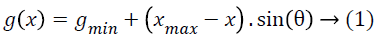
There are two basic topologies of electrostatic generators viz. area-overlap and gap-closing converters [6,9-13]. However they provide small capacitance variation. Hence, a new electret based electrostatic energy harvester with angular electrodes, shown in Figure 1a, has been proposed which obtains larger capacitance variation with respect to displacement of the generator mass. One such triangular electrode structure based electret-free harvester has been proposed [14]. Figure 1b shows the schematic view of the proposed electret based angular electrode structure wherein θ is the angle of the electrodes, L0 the initial electrode fingers overlap length, L is the length of an electrode finger and WF its width. The capacitance between the inter-digitated electrodes is dependent on the height of the electrode fingers HF which is equal to the device layer thickness, gap g (x) between the electrodes and the overlap length l (x). The total capacitance of the proposed harvester consists of two components viz., capacitance due to gap closing of electrode finger tips and capacitance due to gap and area overlap variation. The gap g (x) between the electrodes is a linear function of displacement x and is given as

Figure 1: (a) Schematic view of the layout of the proposed electret based electrostatic energy harvester depicting electret layer over fixed electrodes, springs and movement of direction (b) Zoomed view of an angled electrode structure.
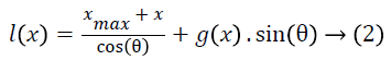
The overlap length of the inter-digitated electrodes can be computed as
The capacitance due to gap closing of finger tips is given as
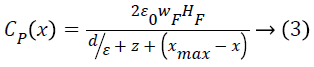
Where z is the minimum gap between the fingertip and base of the electret layer and ε is the permittivity of the electret.
The capacitance for the single inter-digitated electrode element due to area overlap and gap variations is given as
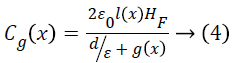
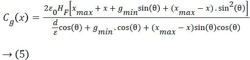
Substituting g (x) and l (x) from Equations 1 and 2 into 4, we get the expression of the capacitance variation with respect to the displacement as
The total capacitance of the proposed electret based energy harvester is given as

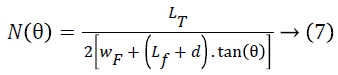
Here CSE (x) is the total capacitance of single electrode structure shown in Figure 2 and N (θ), a function of angle θ, is the number of electrode fingers in the proposed harvester, given as
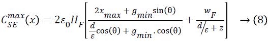
The maximum capacitance of single electrode element can be computed for maximum displacement and is given as
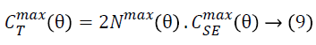
And the total maximum possible capacitance of the proposed electret based harvester can then be computed as
The output of the energy harvester is fed to the converter shown in Figure 2, where Vs is the surface potential of the electret, SW1 and SW2 are the switches which are opened during most part of the conversion process. Cpar is the parasitic capacitance and Cstor is the storage capacitor. The cycle begins with both switches open and the vibrating mass at maximum deflection. The capacitance of the variable capacitor CT is at maximum value (CTmax). SW1 closes and the charge is transferred from the electret surface to the movable electrodes of the capacitor CT. Then SW1 opens and the deflection of the vibrating mass decreases. When the variable capacitance reaches its minimum (CTmin) at x=-xmax, the voltage across the capacitor has to increase. Then SW2 closes and the charge moves to the storage capacitor (Cstor) and the deflection then increases and the next conversion cycle starts again. When the amount of energy on the storage capacitor stays constant, maximum energy is scavenged from the harvester.

Figure 2: Schematic circuit of a basic switching converter for the harvester.
Results and Discussion
The minimum gap between the electrodes gmin is the distance between the electrodes when displacement is maximum x=xmax. Based on the fabrication set-up and limitations [14], the minimum allowable feature size is 2.5 μm, hence the minimum gap gmin must be greater than or equal to 2.5 μm. When simulated in MATLAB, from Equation 1 it is observed that for gmin ≥ 2.5 μm, the angle θ must be greater than 5.74º. For Length (LF) and Width (wF) of electrode finger as 45 μm and 4 μm respectively and the maximum possible displacement xmax of 20 μm, the maximum capacitance of a single electrode structure given in Equation 8 increases with increasing value of θ and the overlap length l (x) approaches to infinity for θ=90º, however due to the design area limitation, it is not possible. Hence, instead of considering CSEmax (x) as the criteria for selecting the value of θ, the variation of maximum total capacitance of the entire structure CTmax (x) at different values of θ is considered. Higher capacitance is achieved for lower values of θ, hence the minimum possible value of θ i.e. 5.74º is selected as the optimal value of the angle of the electrodes to achieve maximum capacitance variation. The capacitance varies inversely with increasing electret thickness d, hence the minimum possible size of 0.5 μm is selected as the electret thickness. For the same design specifications, it is evident from Figure 3 that the proposed harvester provides much better capacitance variation in comparison to the electret based areaoverlap [9] and gap closing harvesters [9]. The converter is able is scavenge a maximum power of around 9.6 μW when the proposed active generator, of layout size 2.5 × 3.5 mm2, is displaced to a maximum value of x=xmax, as shown in Figure 4. A dc-dc converter can further be applied to generate a constant voltage from the harvester.

Figure 3: Performance comparison of capacitance of proposed electret based harvester with other harvester topologies.

Figure 4: Energy generated by the proposed harvester as a function of displacement and capacitance.
Conclusion
SiO2 electret-based angular electrode structure was designed for incorporation into an in-plane electrostatic energy harvester with an aim to provide an alternate energy source to miniaturized cardiac and neural implantable medical devices. Mathematical modeling and analysis showed that the angle θ of the electrodes and the electret layer thickness d are the important design parameters, constrained by the minimum fabrication feature size available to achieve maximum capacitance variations. The results showed that in comparison to standard area-overlap and gap-closing topologies, the proposed harvester provides larger capacitance variation with respect to displacement. The output of the harvester structure when fed to the switching converter is able to scavenge energy up to 9.6 μW at maximum displacement. Thus the proposed harvester, being small in size of only 2.5 × 3.5 mm2 can be used as an energy source for cardiac and neural implants as they consume power in the range of ~10 μW.
References
- Koul S, Ahmed S, Kakkar V. A comparative analysis of different vibration based energy harvesting techniques for implantables. Computing Communication and Automation (ICCCA) International Conference 2015.
- Westerhof N. Cardiac work and efficiency. Oxford Univ Press 2000.
- Deterre M, Risquez S, Bouthaud B, Dal Molin R, Woytasik M, Lefeuvre E. Multilayer out-of-plane overlap electrostatic energy harvesting structure actuated by blood pressure for powering intra-cardiac implants. J Phys IOP Publ 2013.
- Harb A. Energy harvesting: state-of-the-art. Renewable Energy 2011; 36: 2641-2654.
- Lueke J, Moussa WA. MEMS-based power generation techniques for implantable biosensing applications. Sensors 2011; 11: 1433-1460.
- Mitcheson PD, Green TC, Yeatman EM, Holmes AS. Architectures for vibration-driven micropower generators. J Microelectromech Sys 2004; 13: 429-440.
- Vullers R, van Schaijk R, Doms I, Van Hoof C, Mertens R. Micropower energy harvesting. Sol State Electron 2009; 53: 684-693.
- Zhou G, Huang L, Li W, Zhu Z. Harvesting ambient environmental energy for wireless sensor networks: a survey. J Sens 2014; 2014.
- Boisseau S, Despesse G, Seddik BA. Electrostatic conversion for vibration energy harvesting. small-scale energy harvesting. France InTech 2012; 91-134.
- Chiu Y, Kuo C, Chu Y. Design and fabrication of a micro electrostatic vibration-to-electricity energy converter. Cornell Univ Lib 2006.
- Guillemet R, Basset P, Galayko D, Bourouina T. Design optimization of an out-of-plane gap-closing electrostatic Vibration Energy Harvester (VEH) with a limitation on the output voltage. Analog Integr Circ Sig Proc 2012; 71: 39-47.
- Hoffmann D, Folkmer B, Manoli Y. Fabrication, characterization and modelling of electrostatic micro-generators. J Micromech Microeng 2009; 19: 094001.
- Suzuki Y. Recent progress in MEMS electret generator for energy harvesting. IEEJ Trans Electric Electron Eng 2011; 6: 101-111.
- Hoffmann D, Folkmer B, Manoli Y. Analysis and characterization of triangular electrode structures for electrostatic energy harvesting. J Micromech Microeng 2011; 21: 104002.