Research Article - Biomedical Research (2017) Volume 28, Issue 9
Silicon based bio-filter for bio-molecule separation
Praveen Kumar S* and Ramesh T. Aravind RAssociate Professor, Saveetha Engineering College, Tamil Nadu, India
- *Corresponding Author:
- Praveen Kumar S
Associate Professor
Saveetha Engineering College
Tamil Nadu, India
Accepted on February 20, 2017
Abstract
Bio-filter is designed to segregate body fluids into its constituent components like WBC, RBC, platelets from the whole blood using single drop sample of fluid. In this proposed work, separation of biomolecules WBC, RBC and Platelets is possible using passive method based cross flow filtration technique, which is more effective than conventional methods. Separation of biomolecules that are smaller than the microfluidic filter gap size is demonstrated through the sieving medium to filter various sizes of biomolecules with a pre-determined shape and size of microchannel. Filter structure is simple and fluid flow can be achieved without any external force such as electric field, magnetic field, acoustic force, etc. as used in active method. Si material is chosen because of its high biocompatibility. Design is simulated by using COMSOL Multiphysics software. The designed filter can be used for point of care diagnostics and to culture cells.
Keywords
Bio-molecules, Cell separation, MEMS, Microfluidics, Crossflow filtration.
Introduction
Micro Electro Mechanical System (MEMS) is emerging to cater the development of miniaturized devices. MEMS proved to be a revolutionary technology in various domains such as sensors, actuators, fluidics, acoustics, RF MEMS, Optical MEMS, etc. Microfluidics deals with the manipulation and analysis of minute volume of blood [1-3]. MEMS have many applications in microfluidics with building blocks such as flow channels, pumps, needles, mixers, valves, filters, reservoirs and dispensers. Various diseases and malfunctions in human body can be detected by analysing the different components of the blood [4]. Bio-molecule separation is the challenging task.
Two types of cell separation methods are active method and passive method [5]. An active method utilizes external force such as electric field [6-9], magnetic field [10,11], optical interaction [12], acoustic wave [13,14], etc., by using the particle’s electric, magnetic and optical properties. Lack of high throughput and time consuming is the major disadvantage of active devices however they produce high separation efficacy and selectivity.
Passive devices utilize the distinct physical properties of the particle such as size, density and cell deformability [15]. These methods have the simple design and fabrication and relatively high throughput with less input volume. Different methods of designing passive devices are cross-flow filtration [16-19], deterministic lateral displacement [20], centrifugation separation [21], etc. Jafar et al. [22] designed the microfluidic device with pillars placed in the straight rectangular channel for separation of human blood's WBC based on their size. The pillars are grown with space 6 μm. Since it is a dead-end filter, the larger molecules will get blocked at the pillar. To avoid the clogging problem, Yousang et al. developed the μ-sieving technique [5]. In this technique, piezoelectric actuator induces oscillatory vibration in the channel. But it is complicated due to actuator since it need external field.
For biomedical applications, crossflow filtration technique is employed which does not involve any external device to induce the flow of particles. The principle behind the cross-flow filter is that the blood is forced to flow through microfluidic channel parallel to the surface membrane rather than into the filter as in the dead-end filtration. This results in better efficiency. Daniel et al. and Xing et al. have extracted the DNA after cell lysis by using the cross-flow filtration [23,24]. Xing et al. have separated the WBC, RBC and platelets with a tortuous channel which is made of PDMS [23,25]. But some particles are adsorbed on the surface of PDMS which leads to poor efficiency.
In this work, cross flow filtration with Meander shaped microfluidic filter is designed for effective filtration of bio-molecules. Bio-molecules may escape without entering the pores in case of straight microfluidic channel. But in this work, microchannel is designed with bends; the velocity of fluid is decreased at each bend thus controlling the flow rate. Pores are created at each bend of microfluidic channel to increase the filtering efficiency. Silicon material is used in our work and the structure is simulated using COMSOL Multiphysics software.
System Description
The designed microfluidic chip has 3 plates. They are Cover plate, sieving plate and collecting plate as shown in Figure 1.

Figure 1. Structure of blood filtering chip.
Cover plate has inlet and outlet for fluid flow. Filter is designed in Sieving plate and collecting plate will store the filtered bio-molecules.
Meander shaped microchannel with pores is created in the sieving plate to filter the bio-molecules, whose profiles decide the separation efficiency of the blood. Meander shape is shown in Figure 2. The geometrical parameter of designed microchannel is given in Table 1. Silicon material is used for effective filtering of molecules. Pores in the silicon are made possible by Porous silicon formation technique using Electrochemical etching process.

Figure 2. Meander shaped microfluidic Channel.
| Channel Description | Dimension |
|---|---|
| Length | 9.45 mm |
| Width | 250 μm |
| Depth | 100 μm |
| Gap between the bends | 250 μm |
Table 1. Dimensions of meander structure.
Software and Material Specification
COMSOL Multiphysics software is used for simulating and analysing the different meander structures. Laminar flow and particle tracing module is used to track the flow and particle behavior through the microchannel. Silicon material is used as it has more biocompatible properties. Properties of Silicon are given in the Table 2. The blood is chosen as a sample. Important properties of blood are: Density is 1025 Kg/m3 and Dynamic viscosity is 3.5 × 10⁻⁴ PaS.
| Property | Name | Value |
|---|---|---|
| Density | Rho | 2329 (kg/m3) |
| Dynamic viscosity | Mu | 0.8 (Pa.s) |
| Thermal conductivity | K | 130 (W/(m.K) |
| Young’s modulus | E | 170 × 109 (Pa) |
| Poisson’s ratio | Nu | 0.28 |
| Relative Permeability | Mu | 1 |
| Relative Permittivity | E | 11.7 |
Table 2. Properties of silicon.
Results and Discussions
According to the Bernoulli’s principle, the velocity is inversely proportional to pressure across the channel. So when the pressure is high, the velocity (movement) of the bio-molecules in blood will be low. Creating pores where the velocity is low can give high filtering efficiency for bio-medical applications. The symmetric meander shaped microchannel is designed in COMSOL and laminar flow module is used to analyse the flow rate of fluid through the channel. Flow behavior through the microchannel is analysed by designing the structure in 2D model. The blood flow through the inlet is controlled to 0.2 ml/min for effective filtering of bio-molecules. With the flow rate above 0.5 ml/min, the velocity of fluid flow is increased, which leads to poor filtering efficiency. With the flow rate below 0.1 ml/min, the velocity is decreased `and the blood components will not reach till the end of the microchannel so that the separation of bio-molecules becomes less effective. The defined structure is simulated and the velocity flow is given in Figure 3.

Figure 3. Velocity magnitude of microchannel in 2d model.
From the simulation results, it is clear that the velocity of fluid in the channel at each bend is low when compared to the straight microfluidic channel. So, pores are created at each bend for filtering bio-molecules.
Pores of different size, 4 μm for platelets, 8 μm for RBC and 12 μm for WBC, is created at the bends of the micro channel. Symmetric meander microchannel with three pores at the bends is shown in Figure 4.

Figure 4. Structure with different pore size.
The channel with pores is designed and simulated in COMSOL. The laminar flow module is used to analyse the flow behavior and its flow velocity across the channel. Simulation results for velocity profile in the microfluidic channel are shown in Figure 5. The blood flow across the microchannel is shown in Figure 6.

Figure 5. Velocity profile of meander microchannel.

Figure 6. Blood flow across the microchannel.
From Figure 6, it is evident that the blood flows through the channel from the inlet to outlet with the applied velocity. The velocity achieved at the outlet is 2.9 × 10⁻⁵ m/s which is enough for the blood to reach the outlet. The desired bio-molecules are filtered through the pores that are created in the channel. The blood molecules that are penetrating through the pores can be visualized as shown in Figure 7.

Figure 7. Bio-molecule filtration through the pores.
The filtered bio-molecules are received in the collecting plate and can be further processed for clinical assay purposes. The bio-molecules are traced by observing the particle trajectories using the particle tracing module in COMSOL Multiphysics. By assuming the pores created in different position inside the microchannel shown in Figure 8.

Figure 8. (a) and (b) Pores at different positions in channel.
Consider the blood contains n number of bio-molecules (assume n=10). Out of 10 bio-molecules, 9 bio-molecules are trapped from the filter by creating the pores as shown in Figure 8a. But only 4 bio-molecules are filtered by placing the pores as shown in Figure 8b. This is graphically shown in Figure 9. Comparing the above two results, it is evident that pores created as shown in Figure 8a shows better filtering efficiency when compared to pores created as shown in Figure 8b. Bio-molecules are trapped effectively even with irregular input velocities in case of creating pores in bends. But with pores as shown in Figure 8b, the bio-molecules may get escape without reaching the pores.

Figure 9. Time vs. number of filtered molecules.
Theoretical Background
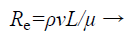
To filter the bio-molecules effectively, the flow through the microfluidic channel should be laminar. Reynolds number decides the whether the fluid flow is laminar or turbulent. Reynolds number, Re is a measure of flow behavior of fluid inside the micro channel. The equation for this dimensionless relation is given by
 (1)
(1)
Where, ρ is the density of fluid
v is the velocity of fluid through the channel
L is the length of channel
μ is the viscosity of fluid
For the flow to be laminar, Reynolds number should be less than 100 in microsized channel else the flow is turbulent. Reynolds number for designed microchannel is calculated to be 62.8 which is less than 100 and thus the flow is laminar. Reynolds number is calculated for different dimensions of microchannel and it is shown in Figure 10. It is clear that as the width of microchannel increases, the Reynolds number increases. For channel with width greater than 250 μm, the calculated Reynolds number with input velocity 0.2 ml/min is greater than 100 and thus the flow becomes turbulent. So the microchannel is designed with width 250 μm. Reynolds number is also calculated for different input velocities which is shown in Table 3.
| Inlet velocity (ml/min) | Reynolds number | Maximum velocity attained at outlet (× 10-5 m/s) |
|---|---|---|
| 0.1 | 50.2 | 2.3233 |
| 0.2 | 62.75 | 2.9041 |
| 0.3 | 71.22 | 3.2913 |
| 0.5 | 83.67 | 3.8721 |
| 1 | 108.77 | 5.0338 |
| 1.5 | 121.32 | 5.6146 |
| 2 | 133.87 | 6.1954 |
| 2.5 | 146.42 | 6.7762 |
| 5 | 184.08 | 8.5187 |
Table 3. Inlet velocity and its corresponding Reynolds number for channel with width 250 μm.

Figure 10. Width vs. Reynolds number.
From the Table 3 it is observed that Reynolds number is increased linearly with respect to inlet velocity. This is because the Reynolds number is directly proportional to the inlet velocity from Equation 1. For inlet velocity greater than 0.5 ml/min, Reynolds number is increased above the critical value. Hence above 0.5 ml/min, the flow becomes turbulent.
To have effective filtering, the structure is designed with multiple bends instead of straight microchannel. As there is bends in microchannel, the velocity (flow speed) of microchannel is reduced and thus more number of bio-molecules can be separated. There will be losses like pressure drop, bend loss, friction loss, etc. that exists at each bend.
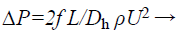
It is easy to characterize the total loss by finding the loss at the single bend. Pressure drop is directly proportional to the inlet velocity and dimension of the microchannel and it given by
 (2)
(2)
Where,
L is the length of the microchannel
Ρ is the density of fluid
U is the velocity of fluid
Dh is the hydrodynamic diameter
Dh=2wd/(w+d) Where w and d is the width and depth of the channel.
The loss due to the pressure drop is related as
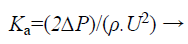 (3)
(3)
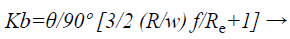
Consider single bend of the designed meander microfluidic channel as shown in Figure 11. Bend loss can be calculated by using Bend loss coefficient which can be determined as

Figure 11. Single bend in meander microchannel.
 (4)
(4)
Where,
θ is the bend angle
R is the bend radius
w is the width of channel
f is friction factor
Re is the Reynolds number
The friction factor is calculated as
f=24/Re (1-1.3553 a+1.9467 a2-1.7012 a3+0.9564a4-0.2537 a5) → (5)
Where,
Re is Reynolds number
a is aspect ratio
Aspect ratio depends upon the width and depth of the channel and can be calculated as
a=(depth of the channel)/(width of the channel) → (6)
So the total loss coefficient will be the sum of the bending loss coefficient and loss due to the pressure drop. The bending loss and loss due to pressure drop for a single bend is calculated and tabulated below in Table 4.
| Reynolds number | 62 |
| Pressure drop (Pa) | 79.12 |
| Loss due to pressure drop | 68.613 |
| Aspect ratio | 0.4 |
| Friction factor | 0.261 |
| Bend loss coefficient | 5.29 × 10³ |
Table 4. Microfluidic parameters.
Conclusion
Thus the biofilter is designed for separation of biomolecules. The flow behavior through the microchannel is analysed and its geometrical parameters are calculated. The theoretical calculations prove that the flow is laminar. This microfilter can separate the RBC, WBC, platelets from whole blood. Silicon based microfilter has the advantage of rapid separation and collecting different biomolecules at the same time. Microfilter overcomes the drawbacks of existing methods for biomolecule separation which is a timely process.
Future Work
The designed biofilter can be implemented in real time by porous silicon for filtration of biomolecules. The electrochemical etching process is the principle for the fabrication of porous silicon. After etching process of porous silicon one unit of blood sample is injected to porous silicon, the filtered biomolecules is verified by using SEM/TEM. Further the filter can be integrated as a chip and it is widely used in application such as cell sorting, cell lysis, DNA amplication, In future biofilter used as a device for counting the RBC, WBC, Platelets in one unit of blood.
References
- Jivani RR, Lakhtaria GJ, Patadiya DD, Patel LD, Jivani NP. Biomedical microelectromechanical systems (BioMEMS): Revolution in drug delivery and analytical techniques. Saudi Pharm J 2016; 24: 1-20.
- Kisore KRT, Vijayalakshmi MA. A review on recent developments for biomolecule separation at analytical scale using microfluidic devices. Analytica Chemica Acta 2015; 906: 7-21.
- Velve-Casquillas G, Le Berre M, Piel M, Tran PT. Microfluidic tools for cell biological research. Nano Today 2010; 5: 28-47.
- Tarn MD, Pamme N. Microfluidic platforms for performing surface-based clinical assays. Expert Rev Mol Diagn 2011; 11: 711-720.
- Yoon Y, Kim S, Lee J, Choi J, Kim RK. Clogging-free microfluidics for continuous size-based separation of microparticles. Sci Rep 2016; 6: 26531.
- Peng Z, He N, Mi JL, Seong HK. Ultra-fast separation of infectious disease-related small dna molecules by single and multi-channel microchiop electrophoresis. Elsevier 2013; 106: 388-393.
- Yuta N, Sakiko H, Takashi Y. Blood plasma separation and extraction from a minute amount of blood using dielectrophoretic and capillary forces. Sensors Actuators 2010; 145: 561-569.
- Bobby M, Anas A, Ghulam D, Hyung JS. Dielectrophoresis based cell switching in continuous flow microfluidic devices. J Electrostat 2016; 84: 63-72.
- Chaohui W, Xiazhang W, Zhuangde J. Dielectrophoretic driving of blood cells in a microchannel. Biotech Biotechnol Equip 2011; 25: 2405-2411.
- Jung Y, Choi Y, Han KH, Frazier AB. Six-stage cascade paramagnetic mode magnetophoretic separation system for human blood samples. Biomed Microdevices 2010; 12: 637-645.
- Pamme N, Eijkel JCT, Manz A. On-chip free-flow magnetophoresis: Separation and detection of mixtures of magnetic particles in continuous flow. J Magn Magnet Mater 2006; 307: 237-244.
- Lin YH, Lee GB. Optically induced flow cytometry for continuous microparticle counting and sorting. Biosens Bioelectron 2008; 24: 572-578.
- Alireza B, Hossein P, Mohsen J, Aminollah M, Peiman M, Alireza FT, Amir SN. Microfluidic intergrated acoustic waving for manipulation of cells and molecules. Biosens Bioelectr 2016; 85: 714-725.
- Fong EJ, Johnston AC, Notton T, Jung SY, Rose KA, Weinberger LS, Shusteff M. Acoustic focusing with engineered node locations for high-performance microfluidic particle separation. Analyst 2014; 139: 1192-1200.
- Elodie S, Herve R, Patrick P, Yves F, Jean LA. Passive microfluidic devices for plasma extraction from whole human blood. Sensors Actuators 2009; 141: 617-624.
- Crowley TA, Pizziconi V. Isolation of plasma from whole blood using planar microfilters for lab-on-a-chip applications. Lab Chip 2005; 5: 922-929.
- Ji HM, Samper V, Chen Y, Heng CK, Lim TM. Silicon-based microfilters for whole blood cell separation. Biomed Microdevices 2008; 10: 251-257.
- Vandelinder V, Groisman A. Separation of plasma from whole human blood in a continuous cross-flow in a molded microfluidic device. Anal Chem 2006; 78: 3765-3771.
- Chen X, Cui DF, Liu CC, Li H. Microfluidic chip for blood cell separation and collection based on crossflow filtration. Sens Actuator B 2008; 130: 216-221.
- Davis JA, Inglis DW, Morton KJ, Lawrence DA, Huang LR, Chou SY, Sturm JC, Austin RH. Deterministic hydrodynamics: taking blood apart. PNAS 2006; 103: 14779-14784.
- Blattert C, Jurischka R, Tahhan I, Schoth A, Reinecke H. Improved plasma yield by a new design of microchannel bend structures. Proc Micro Total Analysis Systems 2006; 359-361.
- Alvankarian J, Bahadorimehr A, Yeop Majlis B. A pillar-based microfilter for isolation of white blood cells on elastomeric substrate. Biomicrofluidics 2013; 7: 14102.
- Xing C, Dafu C, Haoyuan C, Hui L, Jianhai S, Lulu Z. MEMS-based microdevice for cell lysis and dna extraction. Chin Acad Sci 2008.
- Chen X, Cui D, Liu C, Li H, Chen J. Continuous flow microfluidic device for cell separation, cell lysis and DNA purification. Anal Chim Acta 2007; 584: 237-243.
- Jianliang Y, Luis F, Muthukumaran P, Ion S. Modeling the effect of channel bends on microfluidic flow. Micromechatronics Lab 2005.