Research Article - Biomedical Research (2017) Volume 28, Issue 9
Combinational of linear and non-linear agent routing for wireless body area network
NR Ram Mohan1*, S Padmalal2 and B Chitra31Department of Computer Science and Engineering, Sun College of Engineering and Technology, Nagercoil, Tamil Nadu, India
2Department of Computer Science and Engineering, CMS College of Engineering, Namakkal, Tamil Nadu, India
3Department of Electronics and Communication Engineering, Arunachala College of Engineering for Woman, Nagercoil, Tamil Nadu, India
- *Corresponding Author:
- NR Ram Mohan
Department of Computer Science and Engineering
Sun College of Engineering and Technology
Tamil Nadu, India
Accepted on March 13, 2017
Abstract
Wireless Body Area Network (WBAN) is a technology that brings health care to new personalization level. Small sensors are inserted inside the body and monitor person’s physiological state. WBANs monitor an individual’s health in living conditions. The mobile phone in WBAN collects the health data from sensors, store and sends the health care data over wireless links. Routing is an essential one for sending the health care data to the destination with minimum delay and routing overhead. However, energy consumption remained unaddressed. In order to reduce the energy consumption while routing the data packets to the destination, an Integrated Linear and Non-Linear Agent Routing Technique (ILNLAR) is designed. ILNLAR technique in WBAN collects the data packets from different nodes and senses with help of sensing agent. After sensing the data rate gets extracted and classifies the sensed data packets based on emergency and normal conditions. Then, ILNLAR technique performs linear routing and non-linear routing based on nature of the data to reduce the delay and routing overhead. Finally, ILNLAR technique transmits the data packets to sink node in an efficient manner. Performance results shows that the proposed ILNLAR technique obtains the better performance in terms of delay, energy consumption, routing overhead and throughput as compared to the state-of-the-art works.
Keywords
Wireless body area network (WBAN), Health care data, Integrated linear and non-linear agent, Sensing agent, Person’s physiological state, Routing.
Introduction
Wireless Body Area Networks (WBANs) increases the demand of healthcare service to improve the quality of patient’s life. An integrative platform called Integrated Health Monitoring System (IHMS) based on multi-agent model was designed in and increased the elder’s life quality [1]. But, energy consumption still remained a major problem. The adverse effect on BAN reliability is due to the non-protocol-compliant CTI. A Joint Routing and Power Control (JRPC) problem reduces the energy consumption with strong CTI while satisfying the node reachability and delay limitations. A mixed integer linear programming problem (MILP) is designed in and obtained optimal results with IBM’s CPLEX [2]. But, the energy consumption issue remained unaddressed.
A mixed integer linear programming model is an energy aware WBAN model that increases the number and location of relays used and data routing to the sink reduces the network installation cost and the energy consumption by the sensors and relays [3]. However, classification accuracy remained unaddressed. But, the routing overhead is comparatively higher. Elliptic Curve Cryptographic algorithm was designed in with objective of transmitting the patient data throughout the system ensuring the communication between WBAN users [4,5]. Though, the classification accuracy remained a major issue. To increase the classification accuracy, an integer linear programming model was designed in with energy and cost efficient WBAN model. However, non-linear routing remained unaddressed [6].
An agent based healthcare monitoring system using four agents namely, admin agent, control agent, query agent and data agent was presented in resulting in the improvement of data traffic [7,8]. However, the communication delay between sensor nodes remained unaddressed. In addition, QoS-based management scheme was designed in depending on the average filter movement that leads to the enhancement of the patient monitoring ratio [9]. An energy efficient MAC was designed in by policy access schemes for increasing the network lifetime. But, the delay remained unaddressed [10].
In this paper, an Integrated Linear and Non-Linear Agent Routing Technique (ILNLAR) are designed to perform energy efficient routing in WBAN. ILNLAR technique in WBAN collects the data packets from many nodes and senses using sensing agent. Then, the data packets get classified based on emergency and normal conditions. ILNLAR technique performs linear routing and non-linear routing based on nature of the data to reduce the delay and routing overhead.
In the rest of this paper, Section 2 reviews the related work and Section 3 explains the contributions of proposed framework, Integrated Linear and Non-Linear Agent Routing Technique (ILNLAR). Section 4 presents the experimental results and discusses their significance in Section 5. Section 6 finishes the paper with concluding remarks.
Related Works
In a study by Elhadja et al. [11] Multi Attribute Decision Making (MADM) methods was designed to reduce the packet overhead and number of handovers based on network history and user preference. An analysis of QoS aware health monitoring system was presented in the study by Liao et al. [12]. A Virtualization Enabled routing was designed for minimizing the traffic congestion and packet delay [8]. Though, classification accuracy was not at required level. To improve the classification accuracy, Mahalanobis-Taguchi System (MTS) based classification was designed [13]. In a study by Yuvaradni et al. a novel system is planned to reduce the load at hospitals and to present efficient healthcare facility remotely using medical implant communication system and wireless medical telemetry system, an efficient network model joins WBAN and Cloud for data sharing [14]. The network architecture is presented in with four layers like perception layer, network layer, cloud computing layer and application layer. But, the energy consumption remained unaddressed [15].
An open and distributed architecture is designed in with multi agent system for identifying the human postures and harmful action [16]. But, the delay remained unaddressed. An energy-efficient key management scheme is designed in for WBANs with existing resources of node during key management life cycle [17]. Cluster-based hybrid security framework maintains both intra-WBAN and inter-WBAN communications. But, the energy consumption remained unaddressed. The technology and protocols are designed in for finding the WBAN problems to choose the useful solutions for networking area [18].
In a study by Ibarra et al. [19] a joint power-QoS control scheme was introduced by optimal energy usage with best possible QoS. For identifying the human motion, window-based algorithm was used in with optimal features [20]. Despite the energy consumption and delay, to improve increase the energy efficient routing, an Integrated Linear and Non- Linear Agent Routing Technique (ILNLAR) are designed for WBAN that solves the existing issues.
Linear and non-linear agent routing for wireless body area network
A Wireless Body Sensor Network (WBSN) comprises sensor nodes ‘Si’implanted inside human body and sink node ‘SN’ is considered. The designed framework with an intra WBSN is modeled as connectivity graph ‘G’ as given below.
G=(V,E) → (1)
From (1) ‘V’ denotes the vertices forming edges ‘E’. The vertices ‘V’ represents the union of all sensor nodes ‘Si’ and sink node ‘SN’ through relay nodes ‘RNi’ represented as,
V={Si} U {SN} U {RNi} → (2)
The edges ‘E’ in (1) represents the set of wireless link between any two sensor nodes, the relay nodes ‘RNi=RN1, RN2, …., RNn’ in the network and the sink node.
E={e1,e2,…,en} U {SN} U {RNi} → (3)
Each edge possesses the weights that represent network parameters expressed as given below with assumption where each sensor nodes know relay nodes and sink node positions. Figure 1 given below shows the structure of WBAN with source sensor node, a sink node and relay nodes through which linear and non-linear routing is performed.

Figure 1. Structure of WBAN.
Sensor nodes in Wireless Body Sensor Network are energyconstrained and perform sensing task. After sensing, the sensed data gets forwarded to relay nodes from sensor nodes ‘Si’. Consecutively, relay nodes ‘RNi’ routes the information to the sink node ‘SN’. The key aim is to identify set of optimal distances during routing where the energy is consumed at same rate for all sensors in WBAN.
Classification of generated data
The main design focus of Integrated Linear and Non-Linear Agent Routing Technique (ILNLAR) is the provision for Emergency Constrained Data Packets (ECDP) and Normal Data Packets (NDPs). In linear routing of ILNLAR technique, the data collected from the nodes are not directly sent to the sink node. It chooses the neighbouring relay nodes and sends the packet to that node in linear motion then finally it sends to the sink node. Linear routing handles multiple nodes data. In the nonlinear routing, the data collected are directly sent to the sink node. Non-linear routing sends only the emergency nodes data with minimum energy consumption. Consider the emergency as QoS constraint, the ILNLAR technique categorizes the generated data packets into Emergency Constrained Data Packets (ECDP) and Normal Data Packets (NDPs) as shown in Figure 2.

Figure 2. Structure of Generated data classification.
The ECDPs communicates directly with the sink node minimizing the delay time by carrying out non-linear routing. The generated data from electrocardiography (ECG), electroencephalography (EEG), and so on is considered as examples of ECDPs. NDPs failed to include the limitations and therefore linear agent routing is carried out. The wireless body sensor nodes in the network are arranged at equal distance from each other for minimizing the energy consumption. Some of the examples of NDPs include pulse count, blood pressure and so on. Figure 3 shows the energy efficient routing of packets to the sensor data.

Figure 3. Sensor Data Classification algorithm.
As shown in Figure 3, for each sensor nodes, the Sensor Data Classification algorithm classifies the data on the nature of data. To start with, the data rate of each WBAN sensor nodes is measured and compared with the Data Rate Threshold value. Based on resultant comparison value, two routing techniques are used to deliver the health care data to the base station, namely linear agent routing or non-linear agent routing. The routing is carried out based on the nature of data (i.e. emergency or normal data) explained in the following section.
Energy-based linear agent routing
In this section, linear agent routing handles multiple patients’ health monitoring at the same time with minimal energy consumption for NDPs in WBAN. In the linear routing, the data collected from the nodes are not directly sent to the sink node. It sends the data to the direct neighbouring relay nodes and finally it sends to the sink node. The normal data packets are routed in the linear routing process in ILNLAR technique. For routing the data packets, energy parameters is taken as ‘ER’ for receive bit and ‘ET’ for transmit bit over distance ‘d’. The energy used by node for receiving the NDPs from the source is expressed as
 (4)
(4)
The energy used by node for transmitting the NDPs is expressed as
 (5)
(5)
From Eq. (1) and Eq. (2), αR and αT are energy consumed by receiver and transmitter electronics respectively. is the energy dissipated by the power amplifier in NDP transmission. γ represent the path loss exponent. In linear agent routing topology, every sensor sends the data packets to its direct neighbour. When there are many nodes located closely at smallest distance gap, large amount of energy gets consumed by nodes. In order to reduce the energy consumption, it is fine to choose Hn-1 evenly spaced nodes for retransmission in linear agent routing. Hn is optimal number of hop which is calculated by
 (6)
(6)
From Eq. (3), dc is the characteristic distance which is constant. It explains that the nodes are equipped with same radio and propagation environment is constant. The characteristic distance is calculated by,
 (7)
(7)
From Eq. (4), the characteristic distance gets calculated which helps to calculate the hop count. With help of the hop count, the linear agent routing is carried out for NDPs.
Energy-based non-linear agent routing
In this section, non-linear agent routing handles multiple patients’ health monitoring at the same time with minimal energy consumption for ECDPs in WBAN. In non-linear routing, the emergency data packets are directly sent to the sink node. It does not send the data to neighbouring relay nodes. In case of emergency, the nodes choose the non-linear routing for reducing the routing overhead and energy consumption. For non-linear routing, ‘n’ number of sensor nodes and sink node is considered as n+1. In this type of routing, only one source is taken at a time for sending ECDPs and transmission is scheduled without any interference. Every time node is selected as source node (i) or a relay node (j) for connecting the node i. Before choosing the source node or relay node, its flag has to be checked. When the flag is 1, node has failure so the index i gets incremented by 1 or index j gets decremented by 1 based on the node’s flag failure. Then the distance between the source node (xi, yi) and relay node xi, yi are calculated by the distance formula as given below.
 (8)
(8)
From Eq. (5), the minimum distance between the source node and relay node are calculated for transmitting the ECDPs to the destination node with minimum energy conservation. The minimum energy conservation path is identified by
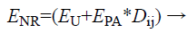 (9)
(9)
From Eq. (6), ‘EU’ denotes energy utilization for finding the route path in non linear routing. Energy used by power amplifier is denoted by‘EPA’ in non-linear routing of data packets. Dij represents the distance between the source node and relay node. Finally, the emergency constrained data packets are sent to the destination in energy efficient manner. An Integrated Linear and Non-Linear Agent Routing Technique (ILNLAR) in WBAN collect the data packets from different nodes and send to the destination in energy efficient manner.
Experimental Settings
Integrated Linear and Non-Linear Agent Routing Technique (ILNLAR) is implemented in NS-2 simulator with the network range of 1500 1500 m size. Sensor nodes 500 are randomly arranged in an area and each sensor node has the similar communication range. Then density is maintained at definite level but progressively enhances the network size by increasing the sensor nodes. In order to maintain the density of the network, once the sensor node increases, the network range is also increased. In each scenario, a total of 10 simulations with 500 sensor nodes are performed to reduce energy consumption and delay. Table 1 illustrates the input parameter.
| Parameters | Values |
|---|---|
| Network area ‘A’ | 1500m * 1500 m |
| Transmission range | 250 meters |
| Number of sensor node | 50, 100, 150, 200, 250, 300, 350, 400, 450, 500 |
| Number of data packet | 10, 20, 30, 40, 50, 60,70, 80, 90, 100 |
| Packet Transmission Time | 250 kbps |
| Mobility model | Random Way Point |
| Network simulator | NS 2.34 |
| Number of simulation | 10 |
| Node pause time | 0-300 seconds |
Table 1. Simulation setup.
Simulation Results and Analysis
Dynamic Source Routing (DSR) routing protocol is used in WBANs with predefined information. The ILNLAR techniques compared against Integrated Health Monitoring System (IHMS) based on multi-agent model [1] and mixed integer linear programming problem (MILP) [2]. The ILNLAR technique conducts experimental works on factors such as energy consumption rate, delay, throughput and routing overhead.
Impact of delay
A delay is the time taken between the departure of collected data packet from source and its arrival to the destination. It is measured in terms of milliseconds (ms).
Delay (ms)=Starting time of packet transmission-Arrival time of packet at Destination → (10)
Table 2 explains the delay with respect to packet number ranging from 10 to 100 in simulation area. When the number of packet gets increased, the delay also gets increased correspondingly. But, the delay of proposed ILNLAR technique is comparatively lesser than that of the IHMS Model [1] and MILP [2].
| Number of Packets (Number) | Delay (ms) | ||
|---|---|---|---|
| IHMS Model | MILP | ILNLAR Technique | |
| 10 | 29 | 21.3 | 15 |
| 20 | 31 | 23.1 | 17 |
| 30 | 33 | 26.4 | 20 |
| 40 | 37 | 27.8 | 22 |
| 50 | 40 | 30.6 | 25 |
| 60 | 43 | 34.5 | 28 |
| 70 | 46 | 37.2 | 32 |
| 80 | 48 | 41.6 | 35 |
| 90 | 52 | 45 | 39 |
| 100 | 56 | 49 | 42 |
Table 2. Tabulation for Delay.
From Figure 4, the simulation results of delay are presented for different number of packets. The sensing agent in ILNLAR senses the information and sends the sensed information to the sink node in WBAN. The data packets are classified into normal and emergency constrained data packets with minimum delay in proposed ILNLAR technique. This in turn reduces the delay using ILNLAR technique by 76% compared to IHMS Model [1] and 36% compared to MILP [2] respectively.

Figure 4. Measure of Delay.
Impact of energy consumption
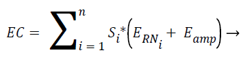
Energy consumption is calculated by analyzing different set of nodes and transmitting amplifiers. It is measured in terms of Joules (J). The energy consumption is the measure for calculating the consumption of energy for routing the packets to the destination. The mathematical formulation for energy consumption ‘EC’ is as given below.
 (11)
(11)
From (11), ‘Si’ represents the number of nodes in WBAN or number of patients to be monitored during health monitoring system and ‘ERNi’ represents the energy consumed for identifying the different relay nodes and ‘Eamp’ is the energy consumed for transmit amplifier.
Table 3 explains the energy consumption with respect to packet number ranging from 10 to 100 in simulation area. When the number of packet gets increased, the energy consumption also gets increased correspondingly. But, the energy consumption of proposed ILNLAR technique is comparatively lesser than that of the IHMS Model [1] and MILP [2]. From Figure 5, the simulation results of energy consumption are presented for different number of packets ranging 10-100 nodes with existing IHMS Model [1] and MILP [2]. Every node in network monitors the energy consumption and maintains battery power drain rate by taking mean value of energy consumption and computes the energy dissipation per second. Compared to the IHMS Model [1] and MILP [2], the proposed ILNLAR technique has less energy consumption while sending the information to the sink node. In addition, the energy consumption in ILNLAR technique is 56% and 28% lesser when compared to IHMS model [1] and MILP [2] respectively.
| Number of Packets (Number) | Energy Consumption (Joules) | ||
|---|---|---|---|
| IHMS Model | MILP | ILNLAR Technique | |
| 10 | 51.45 | 38.69 | 26.54 |
| 20 | 55.63 | 43.54 | 31.29 |
| 30 | 60.48 | 47.89 | 35.89 |
| 40 | 66.98 | 51.69 | 39.18 |
| 50 | 69.56 | 56.87 | 46.83 |
| 60 | 74.36 | 62.47 | 52.47 |
| 70 | 78.36 | 68.35 | 55.98 |
| 80 | 83.96 | 74.56 | 59.12 |
| 90 | 88.47 | 78.96 | 63.54 |
| 100 | 95.65 | 84.26 | 68.91 |
Table 3. Tabulation for energy consumption.

Figure 5. Measure of Energy Consumption.
Impact of throughput
Throughput measures the rate of successful data packets delivery over period of time interval in WSN. Throughput is the ratio of data packets sent by source node and the data packets received by the relay node. It is measured in terms of percentage (%) and is formulated as given below.
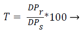 (12)
(12)
From (12), the rate of throughput ‘T’ is measured using the data packets sent ‘DPs’ and the data packets received ‘DPr’. Higher the data packets being received, more efficient the method is said to be.
Table 4 describes the measurement of throughput based on number of nodes ranging from 10-100. The throughput of proposed ILNLAR technique gets increased while increasing the number of nodes compared to existing IHMS Model [1] and MILP [2].
| Number of Packets (Number) | Throughput (%) | ||
|---|---|---|---|
| IHMS Model | MILP | ILNLAR Technique | |
| 10 | 63. 51 | 71.14 | 85.23 |
| 20 | 65.47 | 73.15 | 86.45 |
| 30 | 67.59 | 74.78 | 88.16 |
| 40 | 70.23 | 76.98 | 89.48 |
| 50 | 71.25 | 78.16 | 90.13 |
| 60 | 73.69 | 79.26 | 91.25 |
| 70 | 76.15 | 83.14 | 93.67 |
| 80 | 77.19 | 84.79 | 94.78 |
| 90 | 78.92 | 86.59 | 96.56 |
| 100 | 81.39 | 88.45 | 98.26 |
Table 4. Tabulation for throughput.
From Figure 6, the simulation results of energy consumption are presented for different number of packets ranging 10-100 nodes with existing IHMS Model [1] and MILP [2]. With help of linear agent routing and non-linear routing, throughput gets increased in the proposed ILNLAR technique. Compared to the IHMS Model [1] and MILP [2], the proposed ILNLAR technique has higher throughput while sending the information to the destination node. In addition, the throughput in ILNLAR technique is 20% and 12% higher when compared to IHMS model [1] and MILP [2] respectively.

Figure 6. Measure of Throughput.
Impact of routing overhead (ms)
Routing overhead is defined as the time taken for routing the data packets. The routing overhead is formulated as given below.
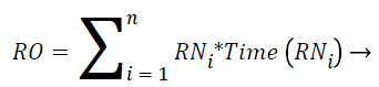 (13)
(13)
From (13), the routing overhead ‘RO’ is obtained with relay nodes ‘RNi’ and the time taken to obtain the neighbouring nodes ‘Time (RNi)’ in the network.
Table 5 explains the energy consumption with respect to packet number ranging from 10 to 100 in simulation area. When the number of packet gets increased, the routing overhead also gets increased correspondingly. But, the routing overhead of proposed ILNLAR technique is comparatively lesser than that of the IHMS Model [1] and MILP [2].
| Number of Packets (Number) | Routing Overhead (ms) | ||
|---|---|---|---|
| IHMS Model | MILP | ILNLAR Technique | |
| 10 | 25 | 18 | 12 |
| 20 | 38 | 29 | 20 |
| 30 | 42 | 35 | 23 |
| 40 | 50 | 41 | 29 |
| 50 | 62 | 48 | 33 |
| 60 | 78 | 55 | 41 |
| 70 | 85 | 61 | 45 |
| 80 | 91 | 68 | 51 |
| 90 | 94 | 75 | 59 |
| 100 | 98 | 82 | 65 |
Table 5. Tabulation for Routing Overhead.
From Figure 7, the simulation results of routing overhead are presented for different number of packets ranging 10-100 nodes with existing IHMS Model [1] and MILP [2]. By using linear agent routing and non-linear routing, routing overhead gets reduced in the proposed ILNLAR technique. Routing overhead in ILNLAR technique is 76% and 36% lesser when compared to IHMS model [1] and MILP [2] respectively.

Figure 7. Measure of Routing Overhead.
Conclusion
An Integrated Linear and Non-Linear Agent Routing Technique (ILNLAR) are designed for routing the information to the sink node from the source node in Wireless Body Area Network (WBAN). ILNLAR technique collects the data packets from different nodes and senses with help of sensing agent. Then sensed data gets classified based on emergency and normal conditions. ILNLAR technique performs linear routing and non-linear routing based on nature of the data to reduce the delay and routing overhead. Finally, ILNLAR technique transmits the data packets to sink node in an efficient manner. The performance of NLAR technique is measured in terms of delay, energy consumption, throughput and routing overhead while routing the information to the sink node in WBAN and compared with IHMS Model and MILP [1,2]. With the simulations conducted for ILNLAR technique, it is observed that the delay gets minimized as compared to state-of- the-art works. The simulations result shows that ILNLAR technique provides better performance by reducing the energy consumption by 42% and delay by 40% when compared to state-of-the-art works.
References
- Lasheng Y, Jie L, Beiji Z. Research on a Multi-agent Based Integrated Health Monitoring System for the Elderly at Home. In: Future Wireless Networks and Information Systems. Springer, Berlin, 2012.
- Hou Y, Li M, Yu S. Making Wireless Body Area Networks Robust under Cross-Technology Interference. IEEE Transac Wireless Commun 2016.
- Elias J. Optimal design of energy-efficient and cost-effective wireless body area networks. Elsevier Ad Hoc Networks 2014; 13: 560-574.
- Prachi KJ. An Energy Efficient Routing Algorithm for Wireless Body Area Network. Int J Wireless Micro Tech 2015; 5: 56-62.
- Mittal M, Chauhan DK. Mobility Maintenance in Wireless Body Area Network. Internat J Latest Trends in Eng G Tech 2015; 5: 04.
- Elias J, Mehaoua A. Energy-aware Topology Design for Wireless Body Area Networks. IEEE Int Conf Commun 2012.
- Vaidehi V, Vardhini M, Yogeshwaran H, Inbasagar G, Bhargavi R, Hemalatha CS. Agent Based Health Monitoring of Elderly People in Indoor Environments Using Wireless Sensor Networks. Elsevier, 2013.
- Porxas AX, Shih-Chun L, Luoz M. QoS-Aware Virtualization-Enabled Routing in Software-Defined Networks. IEEE Int Conf Commun 2015.
- Abreu C, Miranda F, Ricardo M, Mendes PM. QoS-based management of biomedical wireless sensor networks for patient monitoring. Springerplus 2014; 3: 239.
- Jacob AK, Jacob L. Energy Efficient MAC for Qos Traffic in Wireless Body Area Network. Hindawi 2015.
- Elhadja HB, Elias J, Chaari L, Kamoun L. Multi Attribute Decision Making Handover Algorithm for Wireless Body Area Networks. Compute Commun 2016; 81: 97-108.
- Liao Y, Leeson MS, Higgins MD, Bai C. Analysis of In-to-Out Wireless Body Area Network Systems: Towards QoS-Aware Health Internet of Things Applications. Electronics 2016.
- Ali A, Haldar NAH, Khan FA, Ullah S. ECG Arrhythmia Classification UsingMahalanobis-Taguchi System in a Body AreaNetwork Environment. Conf Paper IEEE, 2015.
- Yuvaradni B, Dhanashri D, Sonali G, Gauri T, Thite S. Health Monitoring Services Using Wireless Body Area Network. Imp J Interdiscipl Res 2016; 2: 1648-1651.
- Hassan MM, Lin K, Yue X, Wan J. A multimedia healthcare data sharing approach through cloud-based body area network. Future Gen Compute Syst 2017; 66: 48-58.
- Felisberto F, Laza R, Fdez-Riverola F, Pereira A. A distributed multiagent system architecture for body area networks applied to healthcare monitoring. Biomed Res Int 2015.
- Ali A, Khan FA. Energy-efficient cluster-based security mechanism for intra-WBAN and inter-WBAN communications for healthcare applications. J Wireless Commun Network 2016.
- Filipe L, Fdez-Riverola F, Costa N, Pereira A. Wireless Body Area Networks for Healthcare Applications: Protocol Stack Review. Int J Distributed Sensor Network 2015.
- Ibarra E, Antonopoulos A, Kartsakli E, Joel JPC, Verikoukis C. QoS-aware Energy Management in Body Sensor Nodes Powered by Human Energy Harvesting. IEEE Sens J 2016; 16: 542-549.
- Varkey JP, Pompili D, Walls TA. Human motion recognition using a wireless sensor-based wearable system. Personal and Ubiquitous Computing 2012; 16: 897-910.